Controlling a voltage controlled oscillator in a bang-bang phase locked loop

a voltage controlled oscillator and phase locking technology, applied in pulse automatic control, digital transmission, electronic characteristics varying frequency control, etc., can solve the problems of frequency detector overshoot, frequency detector overshoot, and bang-bang plls, and achieve a wider deadband region, faster pull-in rate, and small pull-in rate

Inactive Publication Date: 2006-05-30
AGILENT TECH INC
View PDF11 Cites 22 Cited by
  • Summary
  • Abstract
  • Description
  • Claims
  • Application Information

AI Technical Summary

Benefits of technology

[0006]In accordance with the invention, the frequency changes in a bang-bang PLL that are generated using a digital phase detector's up / down signal are initially set to produce a faster pull-in rate and are then reduced to produce a smaller pull-in rate. The faster pull-in involves relatively large frequency changes, which allow for a wider deadband region and reduce the negative effects of charge pump leakage. The slower pull-in rate involves smaller frequency changes that enable fine control of the PLL in a regular operating state. The fine control allows the PLL to achieve precise frequency and phase lock.

Problems solved by technology

One problem with PLLs, including bang-bang PLLs, is frequency detector overshoot.
Frequency detector overshoot occurs when the frequency detector causes the VCO frequency to oscillate around the deadband region without being able to drive the VCO frequency into the deadband region.
This can happen if the deadband region is too narrow.
Another common problem with PLLs is charge pump leakage.
A narrower deadband region can remedy this problem, but this may lead to frequency detector overshoot.

Method used


Image

  • Controlling a voltage controlled oscillator in a bang-bang phase locked loop
  • Controlling a voltage controlled oscillator in a bang-bang phase locked loop
  • Controlling a voltage controlled oscillator in a bang-bang phase locked loop

Examples


Embodiment Construction

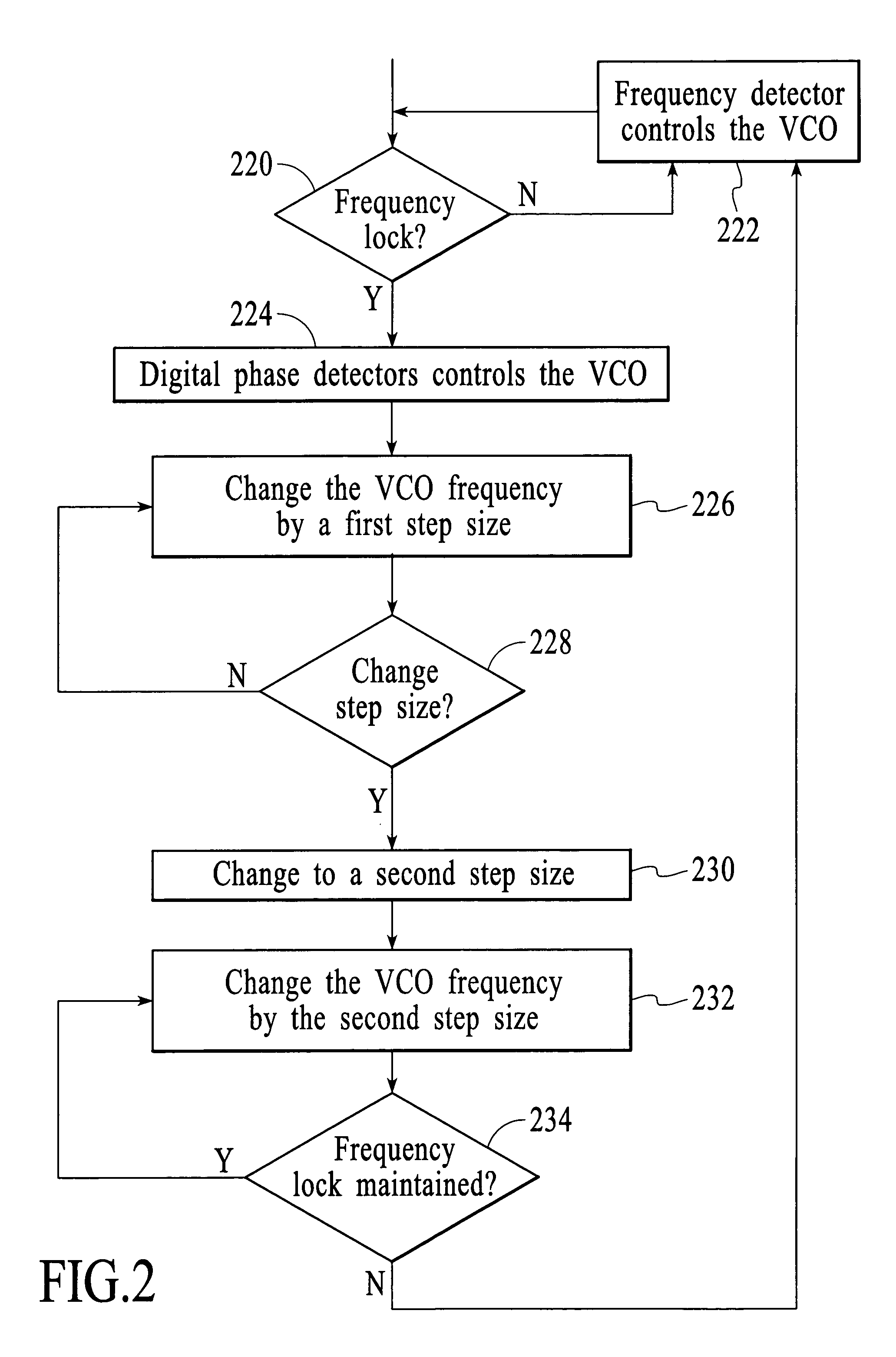
[0025]The task of a PLL is to lock the frequency and phase of a VCO signal to a particular signal, referred to herein as a data input signal (data_in). In PLLs with bang-bang phase detection, the phase detector adjusts the frequency of the VCO signal using a simple up / down signal. In accordance with the invention, the frequency changes produced using an up / down signal are initially set to cause a faster pull-in rate and then reduced to cause a slower pull-in rate. The slower pull-in rate is then maintained during regular PLL operation.

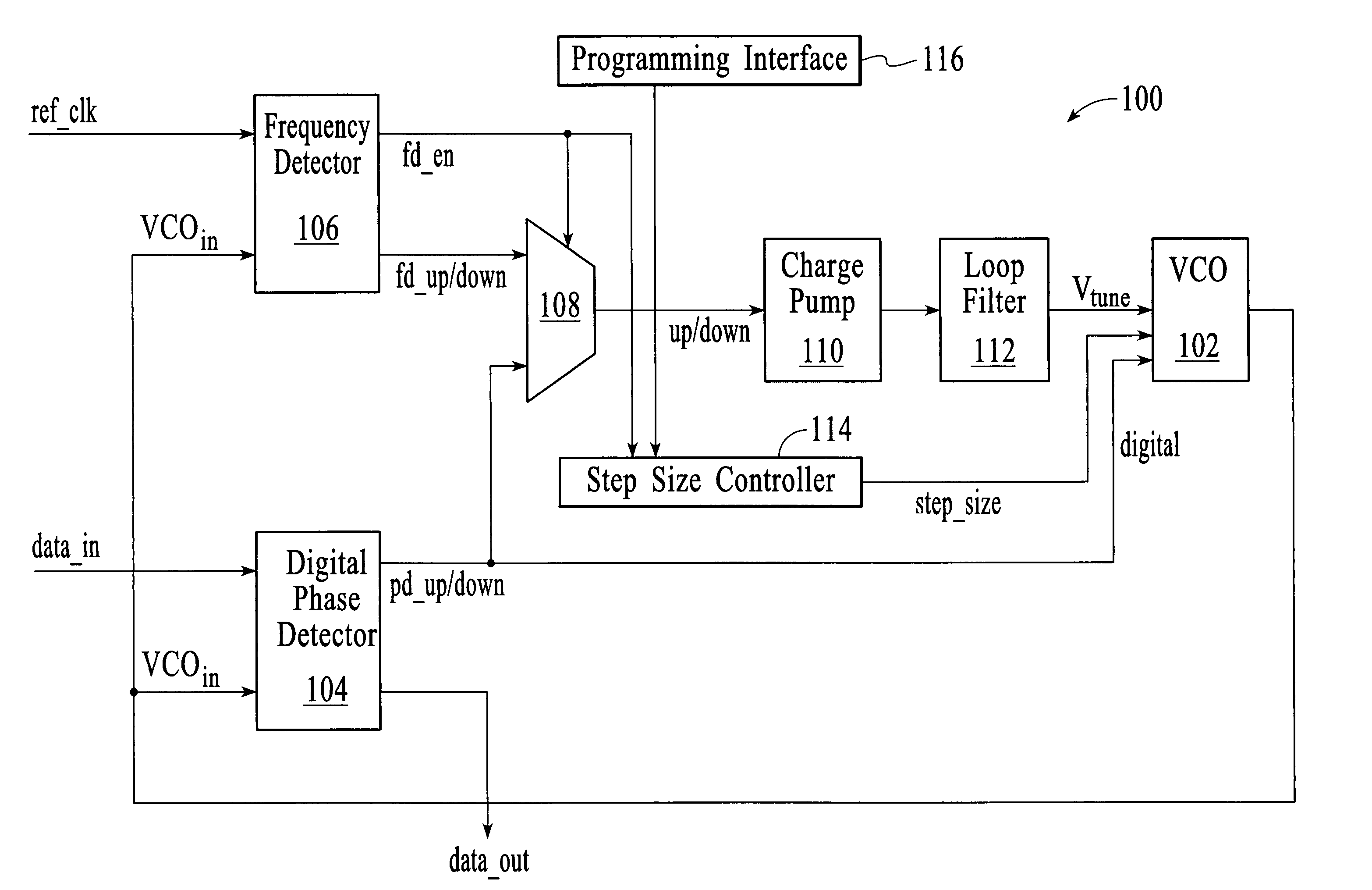
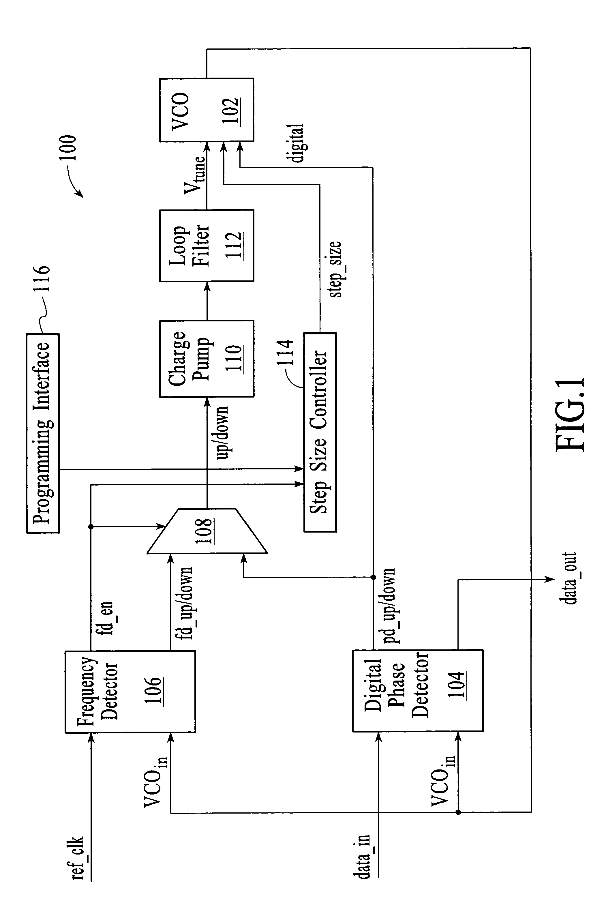
[0026]FIG. 1 depicts an embodiment of a bang-bang PLL 100 that includes a voltage controlled oscillator (VCO) 102, a digital phase detector 104, a frequency detector 106, a multiplexer 108, a charge pump 119, a loop filter 112, and a step size controller 114. The digital phase detector 104 is connected to receive an input signal (data_in) from a signal source and a portion of the VCO signal (VCOin) from the VCO. The input signal carries the data that i...


PUM


Abstract

The frequency changes in a bang-bang PLL that are generated using a digital phase detector's up / down signal are initially set to produce a faster pull-in rate and then reduced to produce a slower pull-in rate. The faster pull-in involves relatively large frequency changes and the slower pull-in rate involves smaller frequency changes. The changes in frequency of a bang-bang PLL can be implemented using a step size controller that includes timing control logic and step size logic. The function of the timing control logic is to control the timing of step size changes. The function of the step size logic is to set the step size of the frequency changes that are made by the VCO in response to the pd_up / down signal that is delivered directly to the VCO from the digital phase detector.

Description

FIELD OF THE INVENTION[0001]The invention relates to phase-locked loops, and more particularly, to controlling the voltage controlled oscillator in a bang-bang phase-locked loop.BACKGROUND OF THE INVENTION[0002]Clock and data recovery (CDR) circuits are widely used when a data signal is sent across a communications link without an accompanying dedicated clock signal. CDR circuits typically use a phase-locked loop (PLL) to determine, from the transitions between physical data values, the exact frequency at which data is arriving and the optimum phase at which to sample the incoming data. PLLs typically include a VCO, a frequency detector, and a phase detector. The phase detector is used to determine the optimum phase at which to sample the incoming data. Phase detectors require that the frequency of a VCO be very close to the frequency of the incoming signal before frequency and phase lock can be achieved. For example, the frequencies of the VCO and incoming signal should be within 0...

Claims


Application Information

Patent Timeline
Patent Type & Authority Patents(United States)
IPC IPC(8): H03L7/06H03L7/00
CPCH03L7/087H03L7/099H03L7/113H03L7/14H03L7/107H03L7/0891H03L7/095H04L7/033H04L7/0083H03L7/1075
Inventor STEINBACH, GUNTER WILLYGALLOWAY, BRIAN JEFFREYKNOTTS, THOMAS ALLEN
Owner AGILENT TECH INC
Why Eureka
Try Eureka