Method and device for emitting pulses on an electricity distribution network

a technology of electricity distribution network and pulse, which is applied in the direction of pulse technique, instruments, coding, etc., can solve the problem that the electric element naturally emits spurious pulses of high frequency, and achieve the effect of less interferen

Inactive Publication Date: 2006-07-18
WATTECO
View PDF13 Cites 15 Cited by
  • Summary
  • Abstract
  • Description
  • Claims
  • Application Information

AI Technical Summary

Benefits of technology

[0011]Thus, the present invention comprises a method for transmitting data via the electricity distribution network, which is less intrusive and causes less interference than the known methods.

Problems solved by technology

The electric element naturally emits a high frequency spurious pulse when it is connected to the network by the closing of the switch means.

Method used


Image

  • Method and device for emitting pulses on an electricity distribution network
  • Method and device for emitting pulses on an electricity distribution network
  • Method and device for emitting pulses on an electricity distribution network

Examples


first embodiment

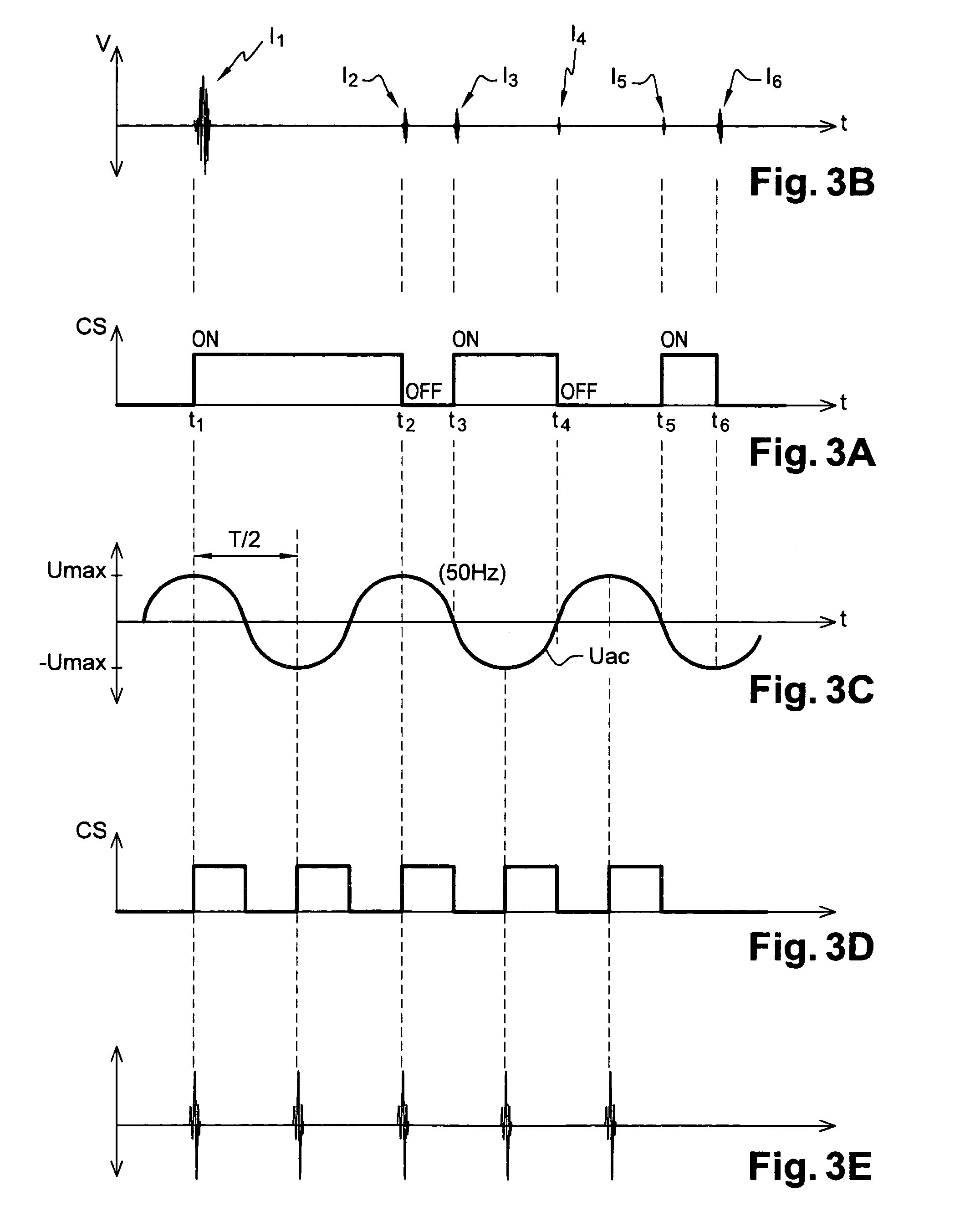
[0075]FIGS. 3D–3E show the method according to the present invention, wherein the opening spurious pulses are neutralized at emission. FIG. 3D represents the shape of the signal CS and FIG. 3E represents the amplitude of the pulses obtained. The signal CS is synchronized with the waveform of the voltage Uac, represented in FIG. 3C. More particularly, the signal CS changes to 1 when the voltage Uac is equal to Umax or −Umax and changes to 0 when the voltage Uac is zero. In other terms, the switch 2 changes from the closed state to the open state when the voltage Uac is zero and the opening spurious pulses I2, I4, I6 are never emitted, as can be seen in FIG. 3E. However, the amplitude of the closing spurious pulses I1, I3, I5 is maximal since the switch 2 is only closed at the instants at which the voltage Uac is maximal.

[0076]It will be understood that the profile of signal CS represented in FIG. 3D only constitutes a template determining the authorized instants of closing and openin...

second embodiment

[0079]the method according to the present invention is, furthermore, provided for sending data or trains of pulses with a higher rate. This embodiment is shown by FIGS. 4A–4C. Here, the closing spurious pulses are not neutralized at emission and are ignored at reception, thanks to an adequate setting of a detection threshold. To determine the instants for authorizing the emission of the spurious pulses, a threshold U1 close to the peak value Umax is chosen, for example a threshold equal to 0.66 Umax. As represented in FIG. 4A, the threshold enables two time windows for authorizing emission TW1, TW2 to be defined, at each half-period T / 2 of the voltage Uac. The window TW1 encompasses the values of the voltage Uac that are positive and higher than U1 and the window TW2 encompasses the values of the voltage Uac that are negative and lower than −U1 (i.e., higher than U1 in absolute value). FIG. 4B represents the template of the control signal CS. The latter comprises trains of closing / o...


PUM


Abstract

A method for emitting a predetermined series of pulses on an electricity distribution network carrying a determined voltage includes linking an electric element to the network by a switch and supplying a control signal to the switch. The switch is driven by the control signal, such that high frequency spurious pulses are emitted at the rate of the control signal. According to one embodiment, the control signal is data bearing, such that data-bearing high frequency spurious pulses are emitted at the rate of the control signal.

Description

BACKGROUND OF THE INVENTION[0001]The present invention relates to a method and a device for emitting a predetermined series of pulses on an electricity distribution network.[0002]The present invention is initially based on ideas and principles set forth in European Patent Application Publication No. EP 1,136,829, the contents of which are incorporated by reference herein. As set forth in this document, any electric apparatus or element, particularly engines, pumps, transformers, electric bulbs, electric or electronic circuits, relative to its electric supply input, has a complex impedance and generates, when switched on and switched off, a high frequency spurious signal having an electromagnetic origin. As this signal is very short in duration, it is designated, in the present application, as forming a “high frequency spurious pulse” naturally emitted by an electric element.[0003]EP 1,136,829 is based on the fact that such a pulse forms a sort of unique signature representative of a...

Claims


Application Information

Patent Timeline
Patent Type & Authority Patents(United States)
IPC IPC(8): H03K7/00H02J3/02H04L25/00G01D4/00G01R22/06H02H1/00H04B3/54
CPCG01D4/004G01R22/063H04B3/542Y04S20/322H04B2203/5412Y02B90/242Y02B90/20Y04S20/30
Inventor BERTRAND, PAUL
Owner WATTECO
Why Eureka
Try Eureka