Aneurysm embolic device with an occlusive member

an embolic device and aneurysm technology, applied in the field of catheter-based implantable medical devices, can solve the problems of affecting the healing effect of the aneurysm, and affecting the healing effect of the aneurysm, and achieve the effect of filling the aneurysm

Active Publication Date: 2006-08-01
CODMAN & SHURTLEFF INC
View PDF27 Cites 154 Cited by
  • Summary
  • Abstract
  • Description
  • Claims
  • Application Information

AI Technical Summary

Benefits of technology

[0015]The sealing member is preferably an expandable flexible disk and is comprised of a circular joining member located at the center of the sealing member. A plurality of reinforcing spokes are attached to the circular joining member and extend radially outward from the circular joining member. A thin circular membrane is bonded to the circular joining member and the reinforcing spokes, and an occlusive member, such as an expand

Problems solved by technology

Aneurysms typically take the form of a balloon-like swelling in the wall of a vessel which generally results from a weakness in the vessel wall.
If untreated, aneurysms may continue expanding until they burst thereby causing hemorrhaging to occur.
If, for example, an aneurysm is present within an artery of the brain, an

Method used


Image

  • Aneurysm embolic device with an occlusive member
  • Aneurysm embolic device with an occlusive member
  • Aneurysm embolic device with an occlusive member

Examples


Embodiment Construction

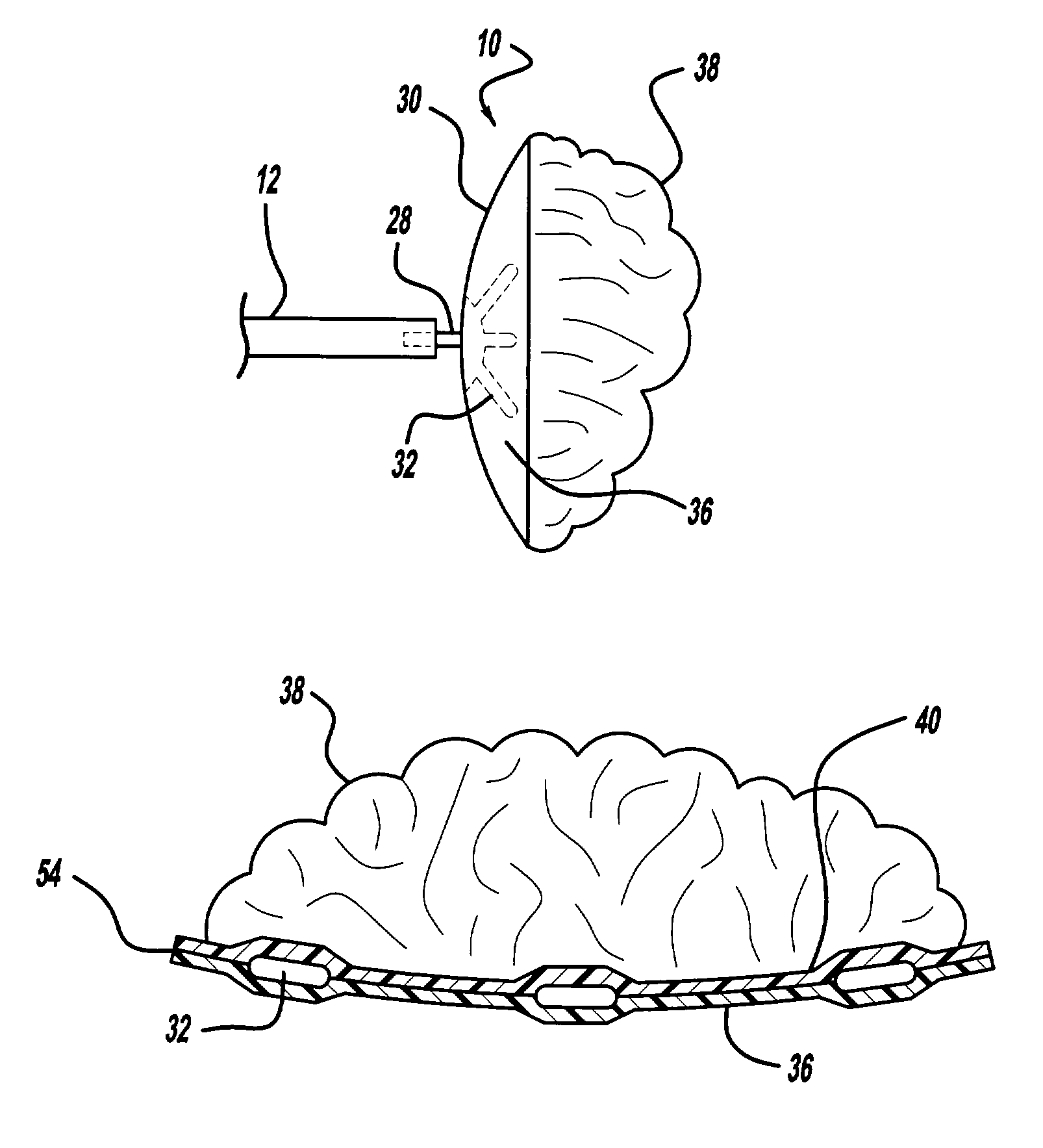
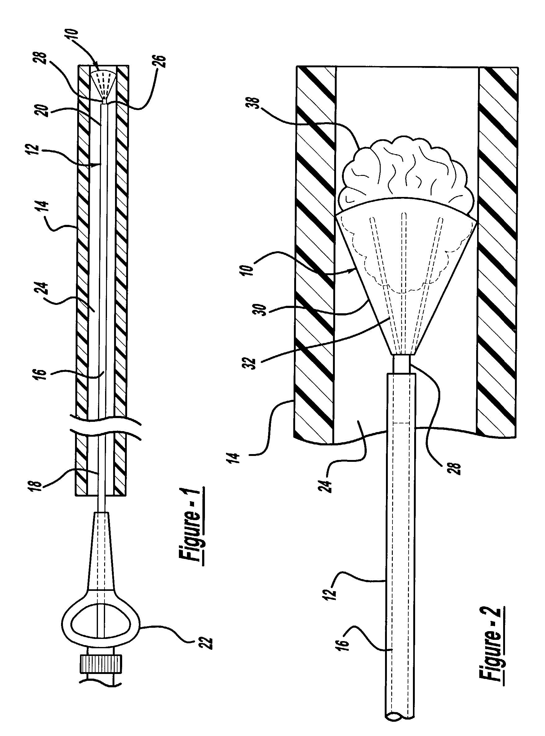
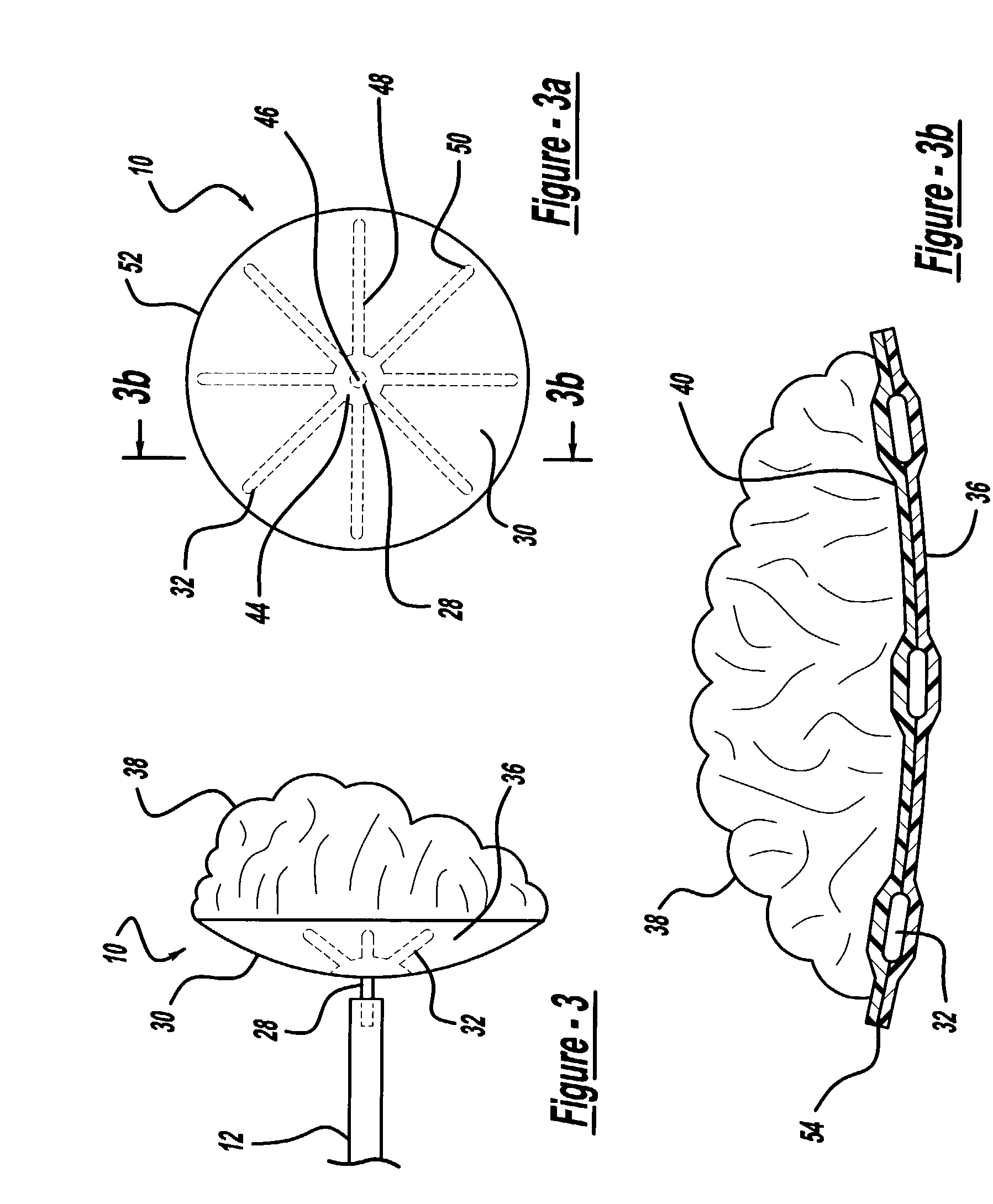
[0028]FIG. 1 illustrates an aneurysm embolic device 10, a deployment catheter 12, and a sheath 14 in accordance with the present invention. The deployment catheter 12 is an elongated tube with a lumen 16. Preferably, the proximal section 18 of the deployment catheter 12 is formed of a pellethane material having a durometer in a range of about 60D to 75D. The proximal section 18 is sufficiently flexible to transverse the vasculature of the human body, but is sufficiently rigid so that it can be pushed distally through the sheath 14. The distal section 20 of the deployment catheter 12 is preferably formed of a pellethane material having a durometer of between 25D and 55D with a durometer of 40D being the preferred durometer.

[0029]The deployment catheter 12 also includes a winged hub 22 coupled to the proximal section 18 of the deployment catheter 12. The winged hub 22 may be made from plastic and aids in the insertion of the deployment catheter 12 into the vasculature of the body. The...


PUM


Abstract

An aneurysm embolic device is disclosed for use in occluding the flow of blood within an aneurysm. The aneurysm embolic device includes an expandable sealing member having a circular joining member and reinforcing spokes which give the sealing member a slightly cupped configuration. The embolic device also includes an occlusive member carried by the expandable sealing member. When the aneurysm embolic device is deployed within the aneurysm, the sealing member expands and the occlusive member fills the aneurysm preventing the flow of blood within the aneurysm.

Description

[0001]This patent application claims the benefit of provisional patent application Ser. No. 60 / 335,489 filed on Nov. 15, 2001.BACKGROUND OF THE INVENTION[0002]1. Field of the Invention[0003]This invention relates to catheter-based implantable medical devices for occluding the flow of blood at a preselected position within a blood vessel, and more particularly to an aneurysm embolic device which serves to fill an aneurysm with an occlusive member thereby preventing the flow of blood into the aneurysm.[0004]2. Description of the Prior Art[0005]Aneurysms typically take the form of a balloon-like swelling in the wall of a vessel which generally results from a weakness in the vessel wall. If untreated, aneurysms may continue expanding until they burst thereby causing hemorrhaging to occur. If, for example, an aneurysm is present within an artery of the brain, and the aneurysm should burst with resulting cranial hemorrhaging, death could occur.[0006]Aneurysms result from many different ca...

Claims


Application Information

Patent Timeline
IPC IPC(8): A61B17/08A61B17/00A61B17/12
CPCA61B17/12022A61B17/12113A61B17/1219A61B17/12172A61B2017/1205A61B2017/00539
Inventor AVELLANET, ERNESTOLULO, ROBERT
Owner CODMAN & SHURTLEFF INC
Why Eureka
Try Eureka