Systems and methods for deploying a biosensor with a stent graft

a biosensor and stent technology, applied in the field of implantable medical devices, can solve the problems of threatening the life of patients, affecting the quality of life of patients, and requiring extensive recovery time,

Inactive Publication Date: 2005-01-11
REMON MEDICAL TECH
View PDF7 Cites 144 Cited by
  • Summary
  • Abstract
  • Description
  • Claims
  • Application Information

AI Technical Summary

Benefits of technology

The implantation catheter preferably includes a tapered nose portion on the distal end that defines a cavity for receiving the biosensor therein when the stent graft is received on the distal region. The sheath preferably includes a tongue or other fle

Problems solved by technology

An aneurysm is a weakening of a wall of a blood vessel that generally results in a ballooning of the wall, and, if left untreated, may result in a rupture that may seriously threaten the life of a patient.
Such surgical approaches, however, may involve extensive recovery times, may be complicated because of the difficulties in suturing the graft to the vessel, and/or may be unsuitable for many at-risk patients because of the high mortality and morbidity rates associated with a surgical intervention of this magnitude.
One potential complication that may occur after a stent graft is implanted is the formation of an endoleak.
If fluid leaks into the aneurysmal sac, it may increase the pressure or endotension within the aneurysm, possi

Method used


Image

  • Systems and methods for deploying a biosensor with a stent graft
  • Systems and methods for deploying a biosensor with a stent graft
  • Systems and methods for deploying a biosensor with a stent graft

Examples


Embodiment Construction

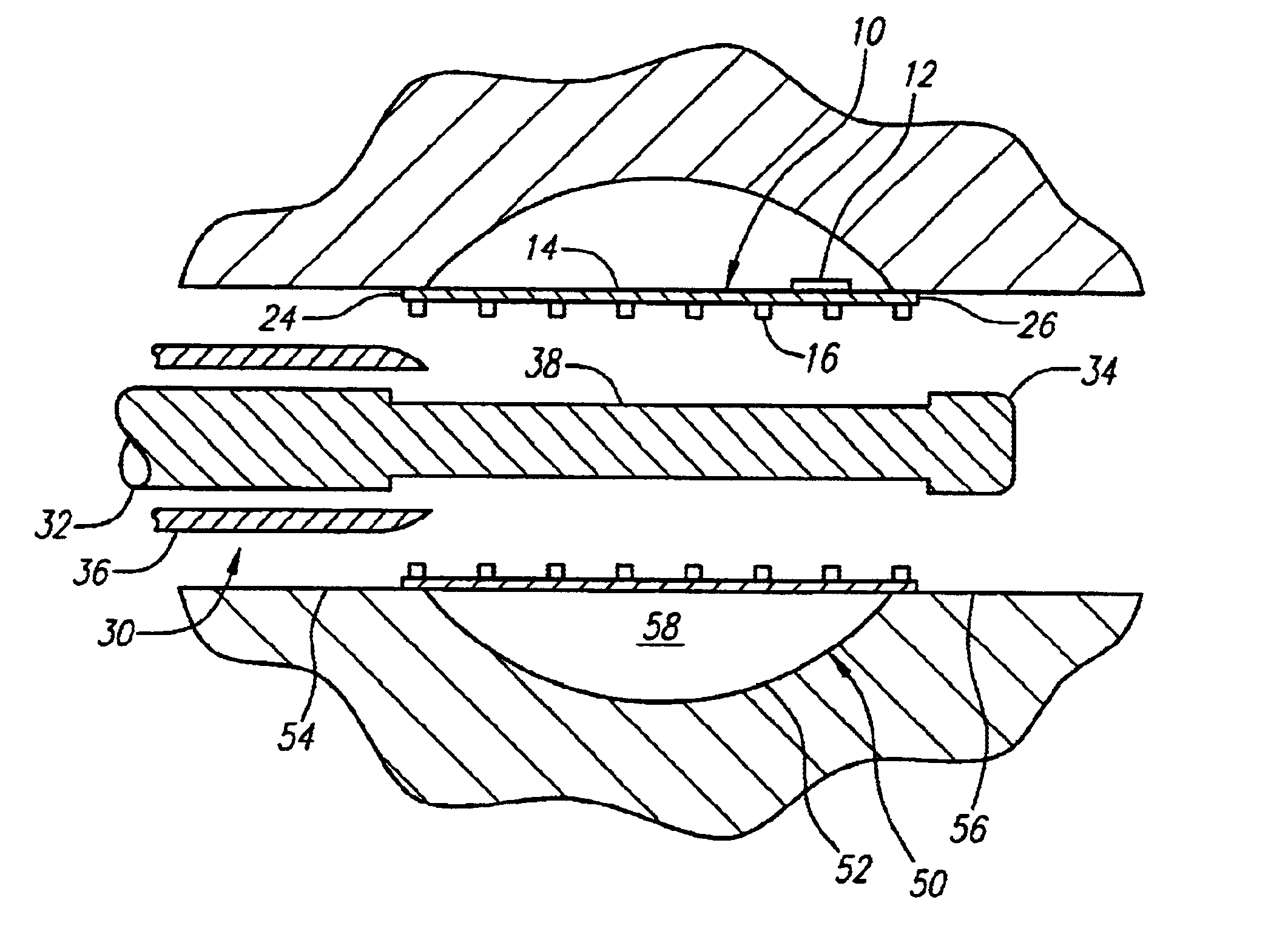
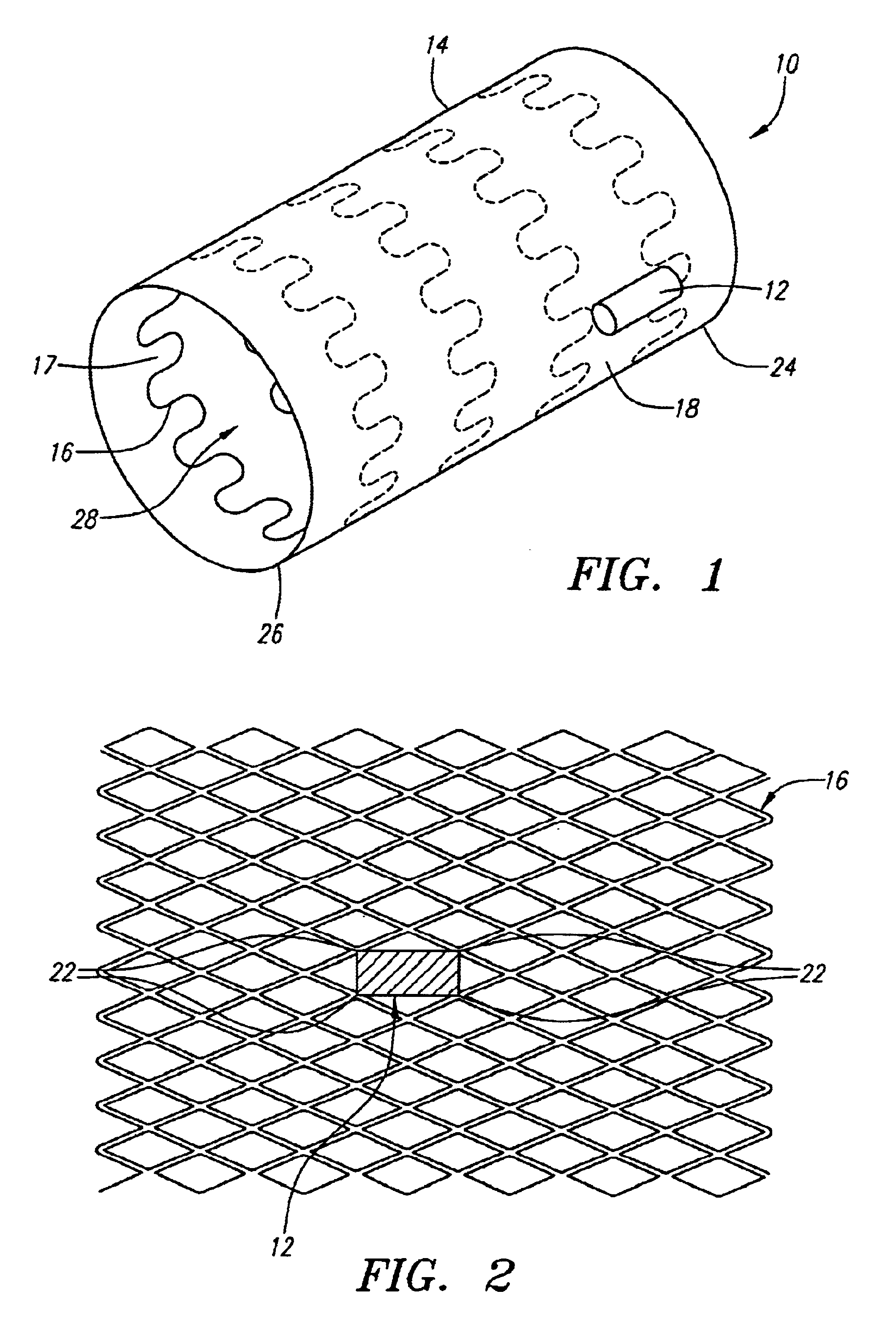
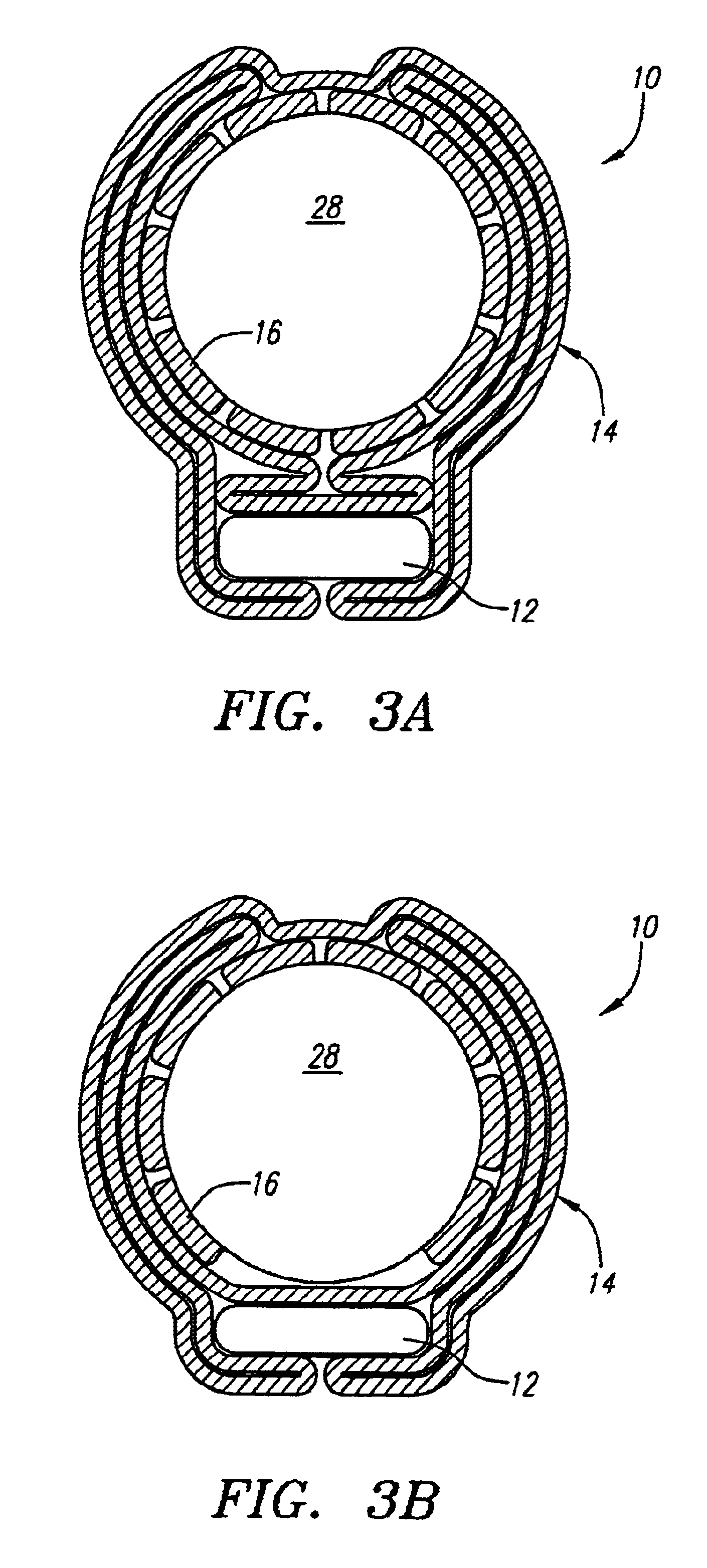
Turning now to the drawings, FIG. 1 shows a first preferred embodiment of a stent graft 10 with an attached biosensor 12, in accordance with the present invention. The stent graft 10 generally includes a tubular prosthetic graft 14, and a support structure 16 attached to the graft 14. The graft 14 may be provided from a substantially non-porous bio-compatible material, such as Dacron or ePTFE, that is formed into a tubular shape. The material is substantially flexible, thereby allowing the graft 14 to be rolled or folded into a reduced profile, accommodating delivery through tortuous anatomy, and / or facilitating implantation within curved blood vessels.

The support structure 16 is preferably a tubular stent that extends along an inside surface 17 of the graft 14 for substantially the entire length of the graft 14. The support structure 16 may be attached to the graft 14 in a variety of ways, such as by sutures, wires, sonic welding, adhesives, and the like, as is well known in the ar...


PUM


Abstract

A stent graft includes a tubular prosthetic graft, a support structure expandable between contracted and enlarged conditions, and a biosensor attached thereto. The biosensor may be directly attached to an outer surface of the graft, to struts defining the support structure, or by one or more filaments configured to dispose the biosensor beyond an outer surface of the stent graft. When the biosensor is attached by one or more filaments, the stent graft is mounted in a contracted profile on a delivery apparatus with the biosensor disposed adjacent to the stent graft thereon. The stent graft is introduced into a blood vessel in the contracted profile, and advanced endolumenally until it is positioned across an aneurysm. The stent graft is expanded towards an enlarged profile such that ends of the stent graft engage healthy regions of the vessel adjacent to the aneurysm, thereby isolating the aneurysm from the rest of the vessel with the biosensor disposed within the aneurysmal sac, the biosensor allowing remote monitoring of pressure or other conditions to detect an endoleak or excessive pressure therein.

Description

DESCRIPTION1. Field of the InventionThe present invention relates generally to implantable medical devices for monitoring internal physiological conditions of a patient, and, more particularly, to a stent graft having a biosensor attached thereto for remotely monitoring physiological conditions of a patient, such as pressure within an aneurysm cavity across which the stent graft is implanted.2. BackgroundAn aneurysm is a weakening of a wall of a blood vessel that generally results in a ballooning of the wall, and, if left untreated, may result in a rupture that may seriously threaten the life of a patient. The weakening of the wall may be due to injury, infection, or other conditions, such as a congenital defect in the arterial connective tissue. Common forms of such an aneurysm include an abdominal aortic aneurysm (“AAA”), an iliac aneurysm, a bifurcated aneurysm of the abdominal aorta and one or both of the iliac arteries, and a thoracic aortic aneurysm.To treat a patient sufferin...

Claims


Application Information

Patent Timeline
IPC IPC(8): A61B5/07A61B5/026A61B5/00A61B5/0215A61B5/11
CPCA61B5/02014A61B5/076A61B5/14546A61B5/6862A61B5/6876A61B5/01A61B5/0215A61B5/026A61B2560/0214A61B5/14532A61B5/1473A61B5/11
Inventor WOLINSKY, LONEPENNER, AVI
Owner REMON MEDICAL TECH
Why Eureka
Try Eureka