
Intraluminal stent graft

a stent and stent technology, applied in the field of intraluminal stent graft, can solve the problems of long recovery period of up to many months, obvious risks of surgery, and extended hospital stays, and achieve the effect of minimizing the delivery profile minimizing endoleaks and migrations of the stent gra

Inactive Publication Date: 2007-07-12
CORDIS CORP
View PDF8 Cites 222 Cited by
  • Summary
  • Abstract
  • Description
  • Claims
  • Application Information

AI Technical Summary

Benefits of technology

[0009] The invention comprises a modular intraluminal stent graft assembled in situ for treating various conditions in the vasculature of a patient. The modular intraluminal stent graft minimizes the delivery profile of the stent graft and delivery catheter used therefore, and minimizes endoleaks and migrations of the stent graft after emplacement thereof at an intended treatment site. The expandable materials comprising the radially expandable stent segments described herein are preferably self-expanding materials, such as Nitinol, or other such self-expanding materials known in the art, although balloon expandable materials may also be used as the artisan should readily appreciate.
[0010] The modular intraluminal stent graft comprises an expandable primary section and an expandable secondary section. Each of the primary section and the secondary section expands from a crimped state, for delivery thereof to an intended treatment site, to an expanded state when deployed. Ideally, in the crimped state, the modular intraluminal stent graft minimizes a delivery profile thereof to enable delivery via a 12 F-15 F delivery catheter system, for example. Minimizing the number of radially expandable stent segments within the primary section helps to achieve the lower profiled delivery status of the modular intraluminal stent graft and enables the use of the smaller profiled delivery catheter as a result.
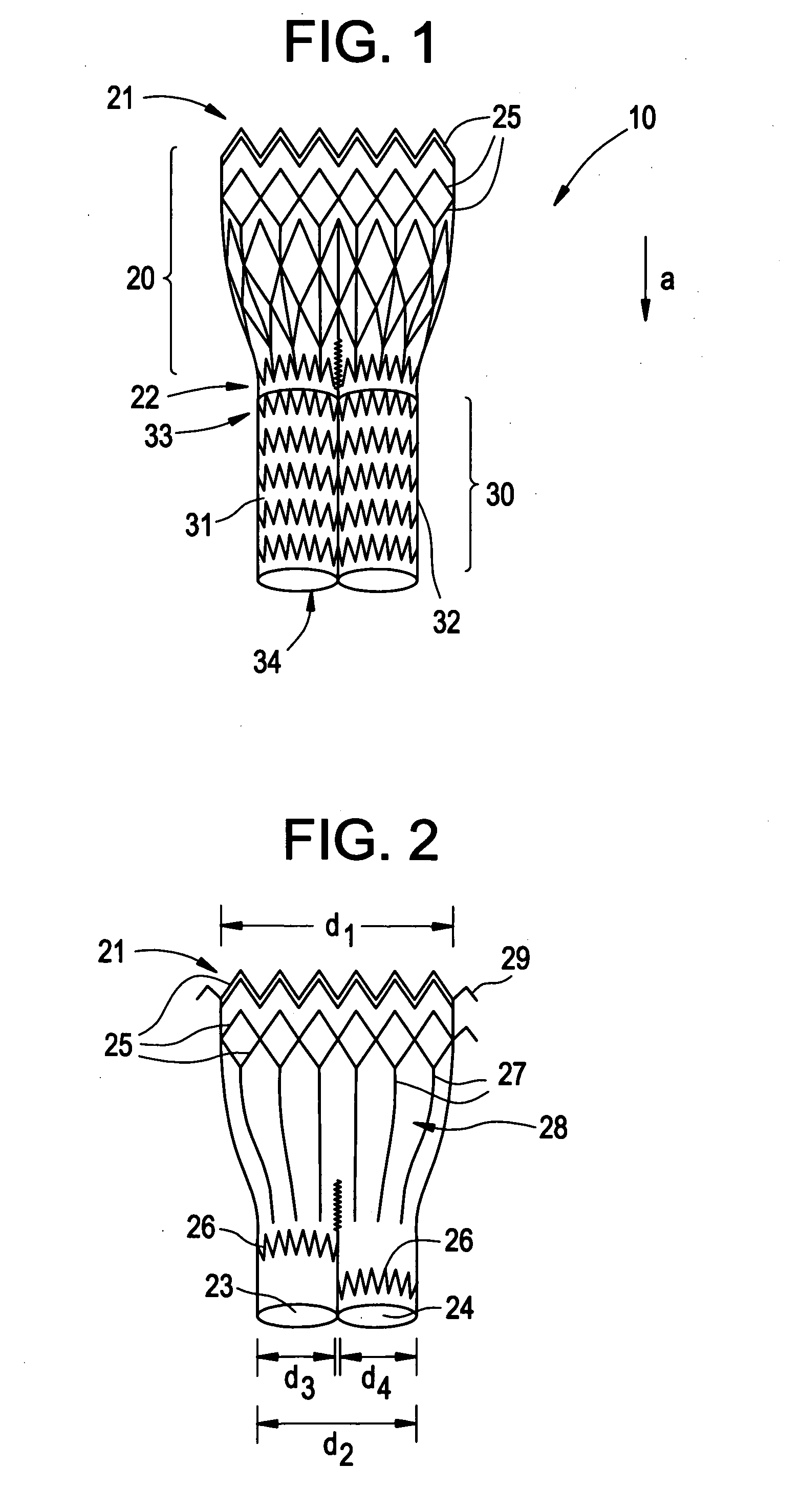
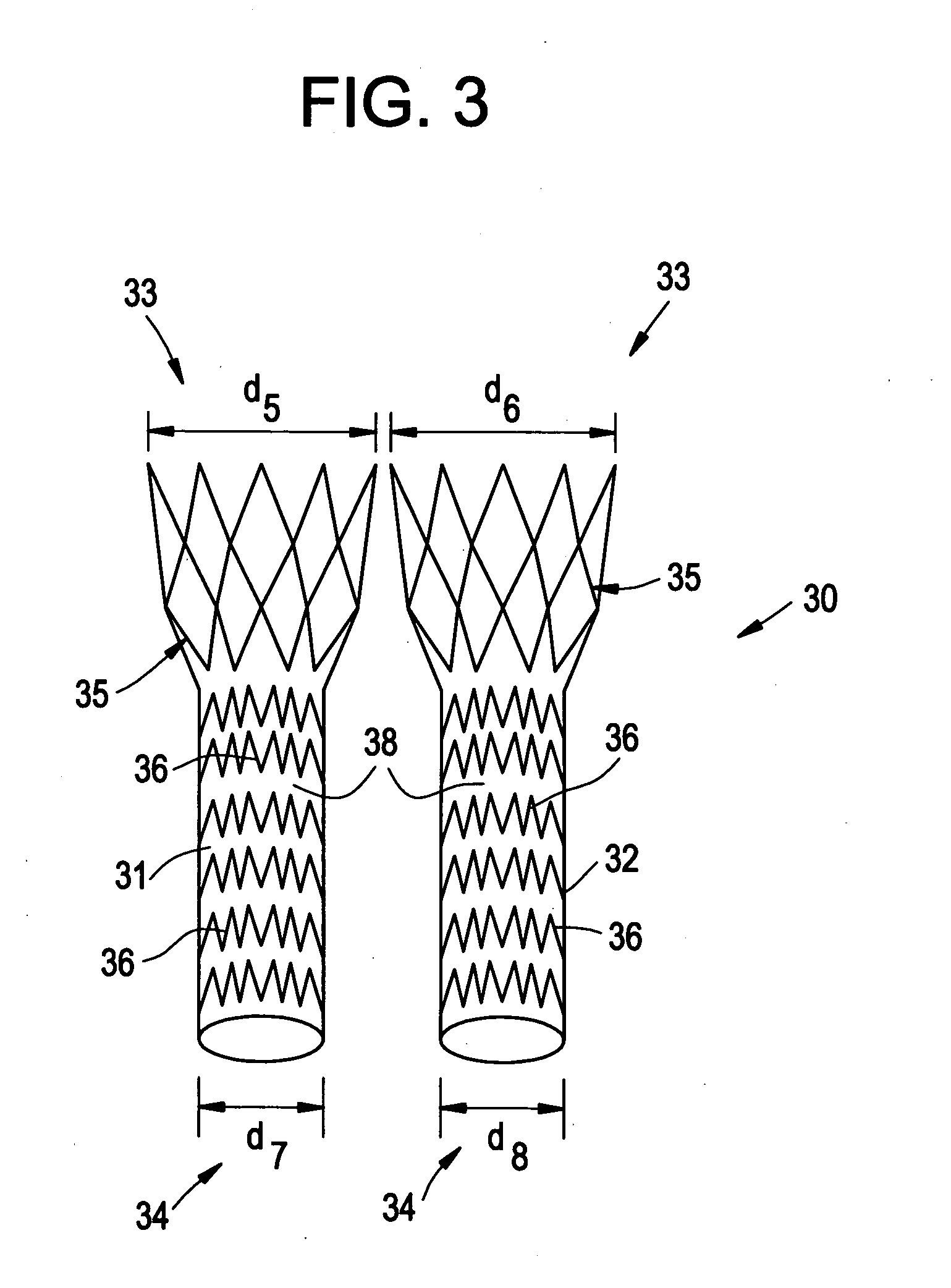
[0012] The secondary section comprises a first endoleg and a second endoleg, wherein the first endoleg is received in situ through the first opening of the primary section and the second endoleg is received in situ through the second opening of the primary section such that an upstream end of each endoleg flares to its expanded state within the region of the primary section otherwise omitting stent segments The flared upstream end of each endoleg comprises radially expanding stent segments that the primary section region otherwise omits. The flared upstream end of each endoleg thus helps to seal and anchor the endoleg within a respective opening of the primary section. Graft material covers the primary and secondary sections. One of the endolegs is thus positioned within one blood vessel branch, whereas the other endoleg is positioned within another blood vessel branch.
[0014] The primary section may further comprise barbs or hooks to help fixate the primary section within the blood vessel at the intended treatment site, such as, for example, the infrarenal aortic neck, or superior to the renal arteries. Downstream ends of one or both of the endolegs may further comprise an expandable section to help anchor the one or both endolegs in place within a blood vessel branch in which the respective endoleg is received, for example, such as to help anchor the one or both endolegs within the ipsilateral or contralateral iliacs branched from the abdominal aorta. Other agents, such as foams, textiles or films may be incorporated onto either or both of the primary section or secondary section to effect an even better seal between the stent graft segments and vasculature, and / or between the primary and secondary sections if desired.

Problems solved by technology

Such surgery poses obvious risks, extended hospital stays, and relatively long recovery periods of up to many months.
The inclusion of stent segments tends to limit the profile reduction of the stent graft however.
Moreover, conventional stent grafts are susceptible to endoleaks, i.e., Type I and III, stent graft disconnection, or migration, particularly where the stent grafts is modular or secured in place by radial forces upon expansion of the stent graft.

Method used


Image

  • Intraluminal stent graft
  • Intraluminal stent graft
  • Intraluminal stent graft

Examples


Embodiment Construction

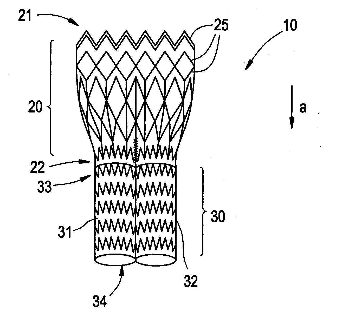
[0022]FIG. 1 illustrates an assembled view of an embodiment of a modular intraluminal stent graft 10 according to the description herein. The modular intraluminal stent graft 10 comprises an expandable primary section 20 and an expandable secondary section 30. Each of the primary section 20 and the secondary section 30 expands from a crimped state, for delivery thereof to an intended treatment site, to an expanded state when deployed. The expanded state is shown in FIG. 1. In the crimped state, the modular intraluminal stent graft 10 ideally minimizes a delivery profile thereof to enable delivery via a conventional 12 F-15 F delivery catheter system, for example. Minimizing the number of radially expandable stent segments within the primary section 20 helps to achieve the lower profiled delivery status of the modular intraluminal stent graft 10. The materials used to comprise the expandable portions of the intraluminal stent graft 10 described herein are preferably self-expandable m...


PUM


Abstract

A modular intraluminal stent graft. The intraluminal stent graft is bifurcated having a primary section and a secondary section extending therefrom. The primary section tapers from a larger diameter at an upstream end to a smaller diameter at a downstream end. The downstream end of the primary section has a pair of independent openings each having an expanded diameter. The secondary section provides a first endoleg having an upstream end that is received through the expanded diameter of one opening of the primary section, and a second endoleg having an upstream end that is received through the second opening of the primary section. The upstream ends of each endoleg, in its expanded state, is larger than the downstream portion of the respective endolegs and expands within the primary section to help assemble the graft in situ. The first and second endolegs also expand within the respective openings each is received within to assemble the stent graft in situ as well. The primary section is positioned within a blood vessel trunk, whereas the endolegs of the secondary section are positioned within a blood vessel branched from the blood vessel trunk. A typical application would be to place the primary section within the abdominal aorta infrarenally, with the endolegs positioned in the ipsilateral and contralaterial iliacs, respectively. By minimizing the number of stent segments in the primary section of the stent graft a lower delivery profile is achieved.

Description

BACKGROUND OF THE INVENTION [0001] 1. Field of the Invention [0002] The invention generally relates to an intraluminal stent graft. More specifically, the invention relates to a bifurcated stent graft assembled in situ for treating vascular aneurysms. [0003] 2. Related Art [0004] Stents are commonly used to repair compromised blood vessels in the body. Such stents may be used to repair compromised coronary arteries which have become narrowed or altogether blocked by the build up of plaque. They may also be used to replace compromised blood vessels, such as the aorta, which have developed enlarged, weakened areas known as aneurysms. In the aorta, aneuryms may often occur in the areas where the aorta divides into two secondary arteries, such as the two common iliac arteries, which supply blood to the lower limbs. [0005] In the past, abdominal aortic aneurysms were frequently repaired by surgery. Such surgery typically required an incision in the patient's body, cutting into the aorta,...

Claims


Application Information

Patent Timeline
IPC IPC(8): A61F2/06
CPCA61F2/07A61F2230/0067A61F2/89A61F2002/067
Inventor DAVILA, LUISFELLER, FREDERICK III
Owner CORDIS CORP
Learn More