Spring loaded bracket assembly having a tool-less attachment and removal feature

a bracket assembly and spring loaded technology, applied in the direction of dismountable cabinets, washstands, lighting support devices, etc., can solve the problems of inconvenient tool use, time-consuming, inconvenient attachment and removal of equipment rack rails, etc., to facilitate the quick and easy removal of the bracket assembly, easy and fast

Inactive Publication Date: 2007-03-20
ERGO 2000
View PDF9 Cites 67 Cited by
  • Summary
  • Abstract
  • Description
  • Claims
  • Application Information

AI Technical Summary

Benefits of technology

[0010]The end portion of the bracket is configured with at least one tab that is engagable with the rail through one of the apertures provided in the rail for the attachment of the brackets. The latch element also includes an outwardly extending latch projection that is configured to enter the rail aperture and abut against the end portion of the bracket assembly when the latching assembly is in the first position. The latch projection includes a tapered leading edge defining a camming surface. When the end portion of the bracket is pushed into position over one of the rail apertures, the engagement between the rail and the leading edge of the latch projection forces the latching assembly from its first position to its second position and against the biasing force provided by the biasing element. This enables the bracket assemb...

Problems solved by technology

One drawback of conventional mounting brackets is that their attachment to, and removal from, an equipment rac...

Method used


Image

  • Spring loaded bracket assembly having a tool-less attachment and removal feature
  • Spring loaded bracket assembly having a tool-less attachment and removal feature
  • Spring loaded bracket assembly having a tool-less attachment and removal feature

Examples


first embodiment

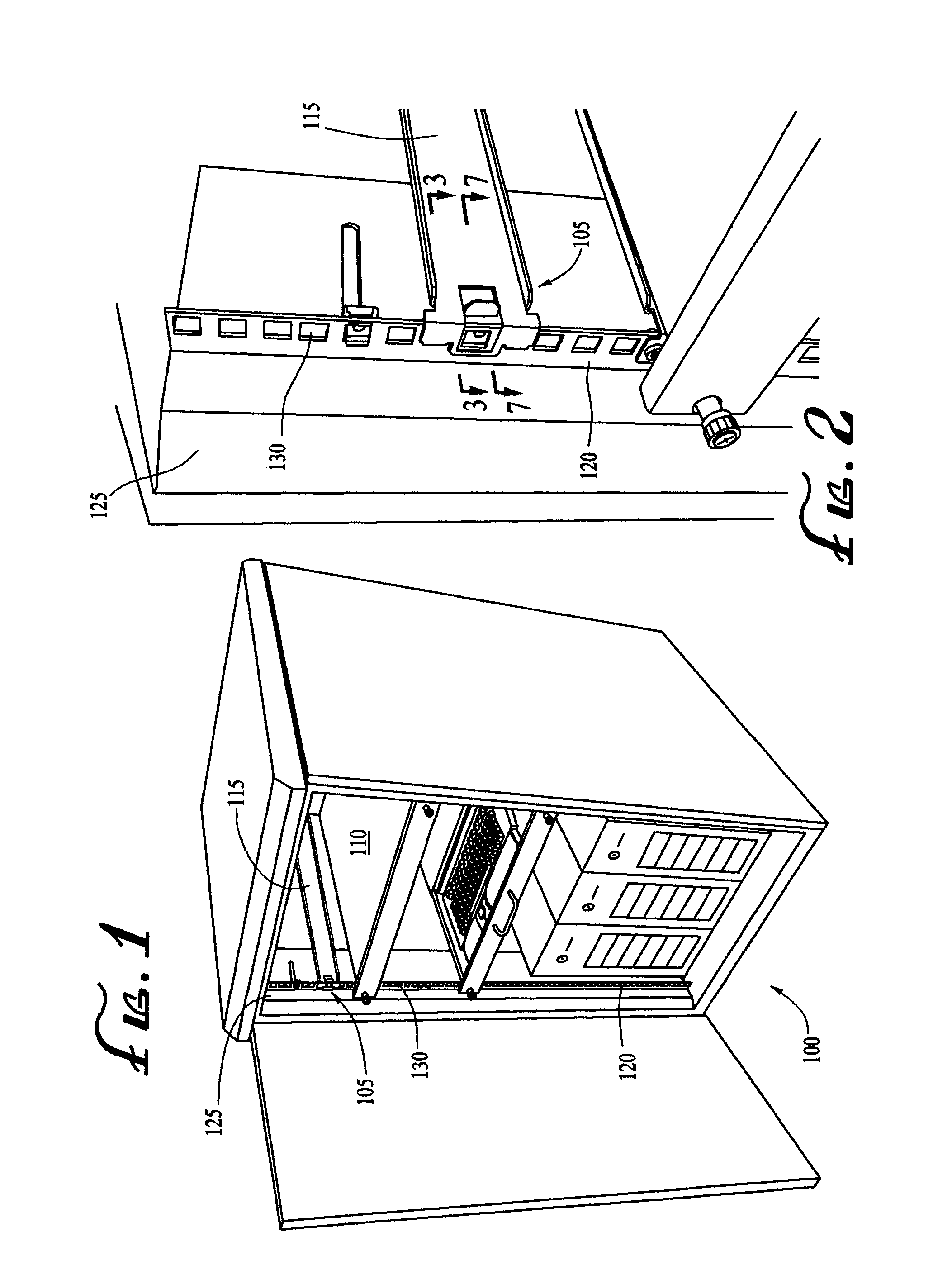
[0041]FIG. 1 is a perspective view of an equipment rack 100 having a bracket assembly 105 according to the present invention. Each of the bracket assemblies 105 (only one of which is shown) includes an attachment portion, as described in detail below, at each end, and a longitudinal main portion having an interior surface 115 that provides a surface for mounting a slide mechanism (not shown), of conventional design.

[0042]The equipment rack 100 also includes a number of shelves 110 having opposed side edges that are configured to slidably engage the slide mechanisms mounted on the bracket assemblies on opposite sides of the rack 100 to enable the shelves 110 to slide in and out of the rack. The shelves 110 are used to hold equipment such as computer monitors, keyboards, and servers, and the slide mechanisms facilitate the movement of the shelves 110 and equipment into and out of the equipment rack 100, in a manner that is well known in the art.

[0043]Inside the equipment rack 100, a v...

second embodiment

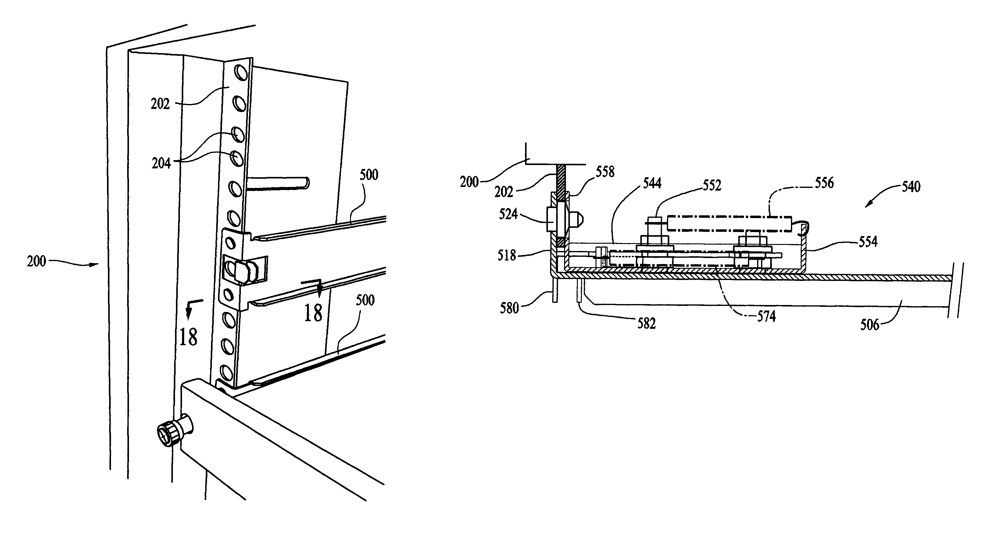
[0056]A second exemplary embodiment of a mounting bracket assembly 500 in accordance with the present invention is illustrated in association with a second equipment rack 200 in the perspective view of FIG. 9. As illustrated in the enlarged perspective views of FIGS. 10–12, the equipment rack typically includes four vertical rails 202, one at each corner thereof, and each of which includes a plurality of through-apertures 204, which, by standard convention, are arranged in spaced groups of three. As is also standard in the industry, the rail apertures may be square, as illustrated in FIG. 10, or alternatively, large, round and unthreaded, as illustrated in FIG. 11, or in yet another alternative, small, round, and internally threaded, as illustrated in FIG. 12. As described in more detail below, a novel alignment pin 524 (see FIG. 17) of the mounting bracket assembly enables it to be aligned and attached to any one of the standard rail configurations illustrated in the figures withou...


PUM


Abstract

A bracket assembly for attaching a slide track to a rail of an equipment rack without the need for tools comprises a longitudinal main portion, a first or interior surface of which provides a mounting surface for the slide track, and an attachment portion that is substantially perpendicular to the main portion, and that is configured to seat against the rail. A quick-release latching assembly, including a latch element, is slidably mounted on a second, or exterior, surface of the main portion of the bracket assembly adjacent to the end portion, and is movable between a first position, in which the latch element is in a locking engagement with the rail, and a second position in which the latch element is disengaged from the rail. The latching assembly is coupled to the main bracket portion by a biasing element, such as a spring or an elastic band, that biases the latching assembly toward the first position.

Description

CROSS-REFERENCE TO RELATED APPLICATIONS[0001]This application claims benefit under 35 U.S.C. Section 119(e) of co-pending provisional patent application Ser. No. 60 / 397,364, filed Jul. 19, 2002.FEDERALLY-SPONSORED RESEARCH OR DEVELOPMENT[0002]Not ApplicableBACKGROUND OF THE INVENTION[0003]1. Field of the Invention[0004]This invention relates, in general, to mounting brackets for equipment racks, and more specifically, to a resiliently biased bracket assembly having a “tool-less” attachment and removal feature, i.e., one which can be attached to and removed from an equipment rack without the use of tools or implements.[0005]2. Description of Related Art[0006]Conventional equipment racks for holding, e.g., computer or telecommunication equipments, typically employ an arrangement of vertical rails, usually one in each interior corner thereof. The racks usually include several shelves that are slidably mounted in a pair of opposing slide tracks, each of which, in turn, is attached to a ...

Claims


Application Information

Patent Timeline
IPC IPC(8): A47B88/00A47B88/04
CPCA47B88/044A47B88/43
Inventor HAMILTON, SCOTT L.
Owner ERGO 2000
Why Eureka
Try Eureka