
Rope light track system

a technology of rope light and track system, which is applied in the direction of lighting applications, color-music apparatus, ways, etc., can solve the problems of reducing the structural strength of the lighting string, limiting the areas in which they may be installed, and affecting the installation of bulbs led's, fibers, etc., and achieves the effect of preventing accidental removal

Inactive Publication Date: 2008-03-25
PATTEN GREGG M
View PDF15 Cites 100 Cited by
  • Summary
  • Abstract
  • Description
  • Claims
  • Application Information

AI Technical Summary

Benefits of technology

[0018]It is therefore an object of the present invention to provide a rope light track system for mounting tubular flexible rope light strings on a generally flat surface, which is easily and quickly installed.
[0019]It is another object of this invention to provide a rope light track system that houses a tubular flexible rope light string for providing interior and exterior structures with utilitarian and aesthetic decorative lighting effects.
[0020]Another object of this invention is to provide a rope light track system that houses a tubular flexible rope light string, that will protect and prevent the light string from being crushed by the wheel of a vehicle, from being stepped on, from becoming twisted or deformed, and prevent damage to the light emitting elements and short circuiting of the interior wiring.
[0021]Another object of this invention is to provide a rope light track system that houses a tubular flexible rope light string that may be easily and quickly installed on a wide variety of interior and exterior structures, such as in or on a concrete driveway or walkway, along baseboards, on stairways and handrails, under cabinets and countertops, and on boat docks.
[0023]A still further object of this invention is to provide a rope light track system that houses a tubular flexible rope light string, which is simple in construction, inexpensive to manufacture and is safe, rugged and reliable in operation.
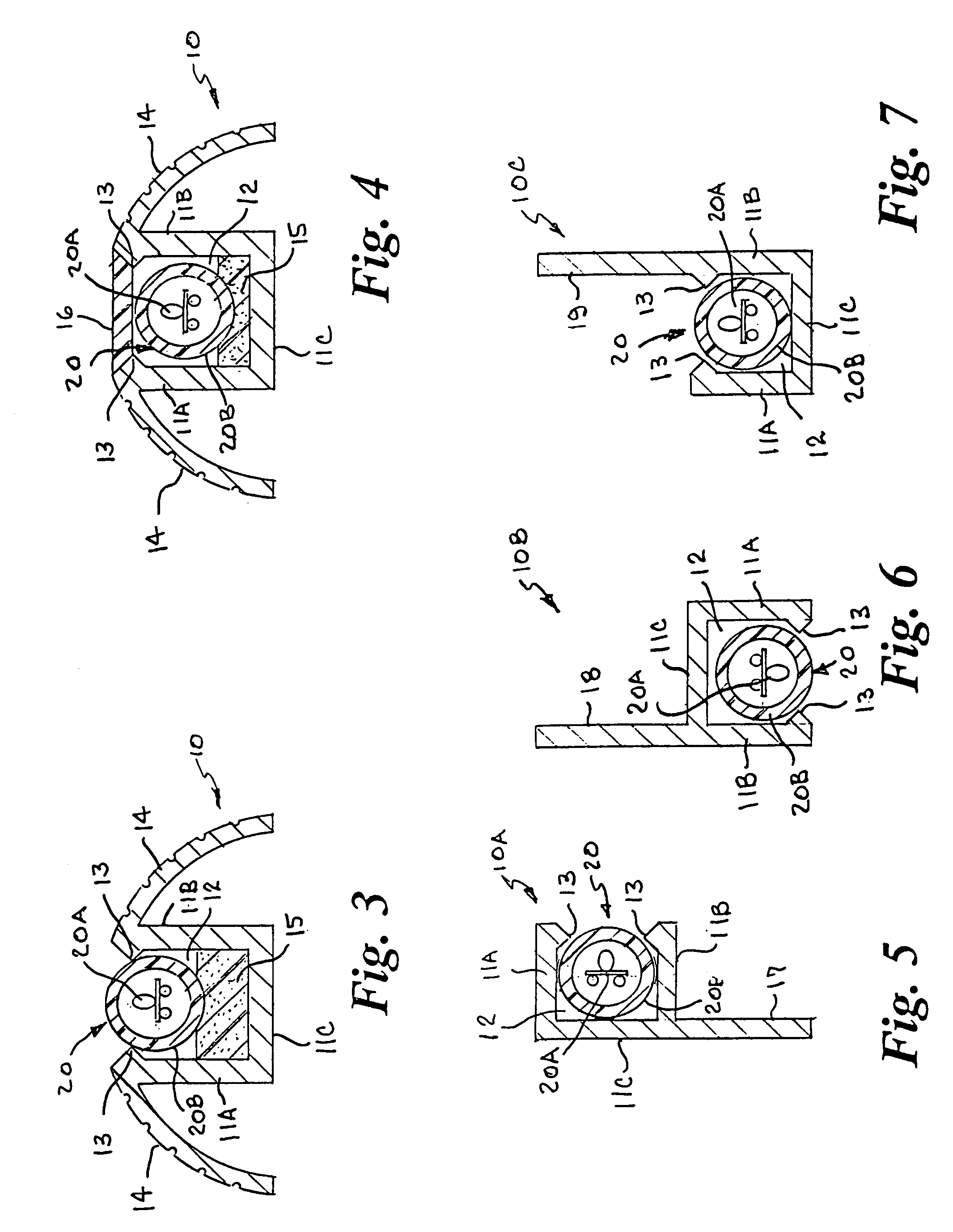
[0025]The above noted objects and other objects of the invention are accomplished by a rope light track system that houses a tubular flexible rope light string and can be mounted on or in various interior and exterior structures to protect the light string from damage and provide utilitarian and decorative lighting. The system includes a plurality of elongate rigid or semi-rigid tracks having a longitudinal generally rectangular U-shaped retention channel with an open end defined by laterally opposed side walls adjoined at one end by a transverse base wall and at least one retainer element near the open end. The tracks have side portions or a mounting flange portion extending outwardly from the retention channel to accommodate various mounting configurations. An elongate tubular flexible rope lighting string is removably mounted in the retention channel and retained therein to prevent accidental removal, and is disposed below the channel open end to protect it from being damaged and allow light emanating therefrom to be directed out of the channel open end. Various control devices control the illuminating operation of the rope light string.

Problems solved by technology

Although the flexible tube allows users to configure these types of flexible lighting strips or rope lights into various configurations with ease, it also reduces the structural strength of the lighting string, and limits the areas in which they may be installed.
For example, if used to border a driveway, walkway, or stairway, they may be crushed by the wheel of a vehicle, or may be stepped on; or if placed on a handrail, they may be become twisted or deformed, resulting in damaged bulbs LED's, or fibers, or short circuiting or the wiring in the flexible tube.

Method used


Image

  • Rope light track system
  • Rope light track system
  • Rope light track system

Examples


Embodiment Construction

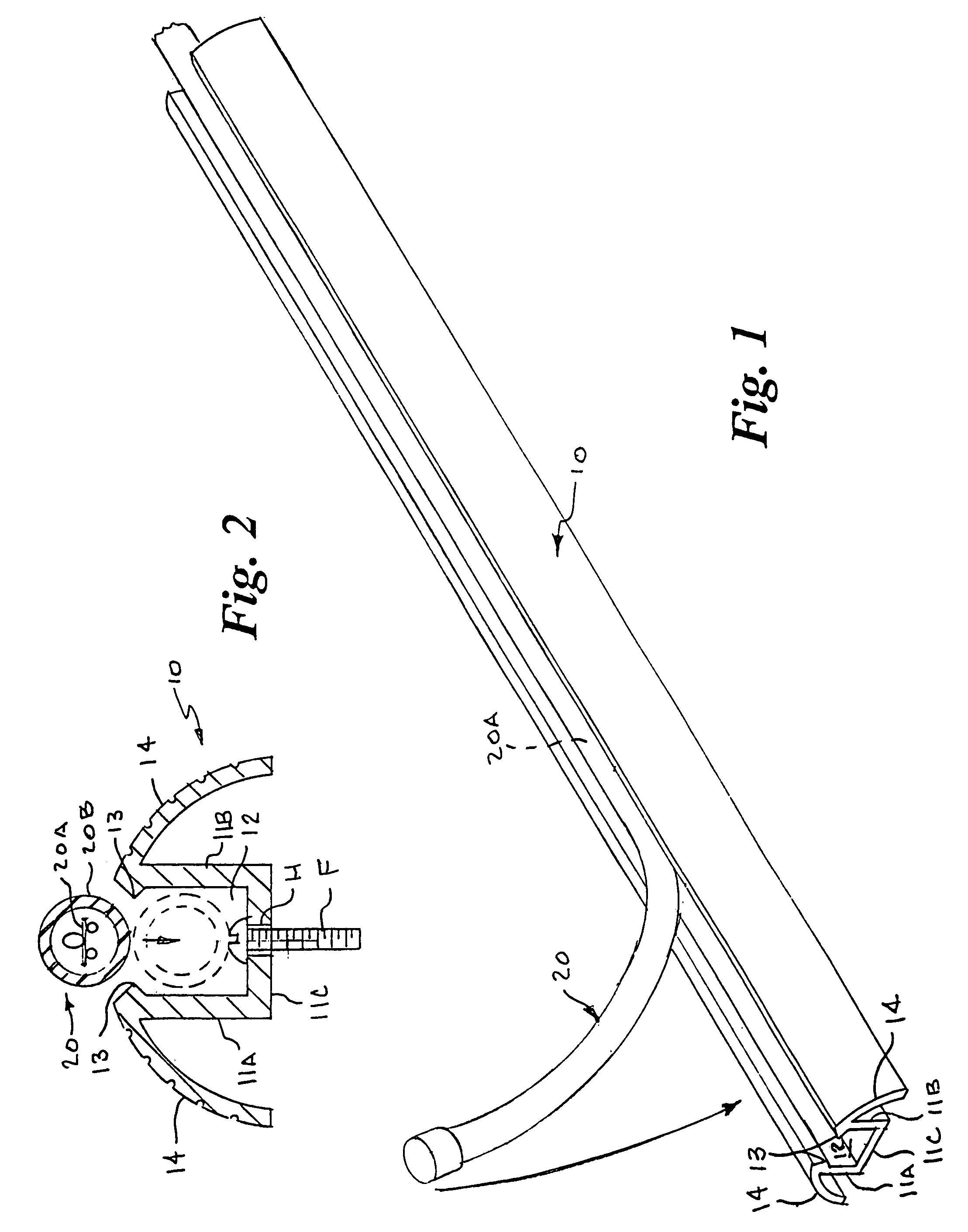
[0035]As used herein, the terms “flexible tubular light string” and “rope light string” mean a lighting assembly having a light emitting source encased in an elongate hollow flexible translucent tube. It should also be understood that the light emitting source encased in the flexible tube may be, but not limited to, a plurality of closely spaced electrically connected miniature light bulbs or light emitting diodes (LED's) to form elongate strings, or elongate side-lit fiber optic cable. The rope light track system includes a plurality of tracks that may be installed end-to-end on a wide variety of interior and exterior structures and in which an elongate rope light string is removably mounted to provide utilitarian and aesthetic decorative lighting effects.

[0036]Referring now to FIGS. 1 and 2 of the drawings by numerals of reference, there is shown a first embodiment of a track member 10 having first and second parallel laterally spaced side walls 11A, 11B, each adjoined at a first ...


PUM


Abstract

A rope light track system houses a tubular flexible rope light string and can be mounted on or in various interior and exterior structures to protect the light string from damage and provide utilitarian and decorative lighting. The system includes a plurality of elongate rigid or semi-rigid tracks having a longitudinal generally rectangular U-shaped retention channel with an open end defined by laterally opposed side walls adjoined at one end by a transverse base wall and at least one retainer element near the open end. The tracks have side portions or a mounting flange portion extending outwardly from the retention channel to accommodate various mounting configurations. An elongate tubular flexible rope lighting string is removably mounted in the retention channel and retained therein to prevent accidental removal, and is disposed below the channel open end to protect it from being damaged and allow light emanating therefrom to be directed out of the channel open end. Various control devices control the illuminating operation of the rope light string.

Description

CROSS REFERENCE TO RELATED APPLICATION[0001]This application claims priority of U.S. Provisional Patent Application Ser. No. 60 / 581,170, filed Jun. 18, 2004, the pendency of which is extended until Jun. 20, 2005 under 35 U.S.C. 119(e)(3).BACKGROUND OF THE INVENTION[0002]1. Field of the Invention[0003]This invention relates generally to flexible strip lighting fixtures and systems, and more particularly to a rope light track system that houses a tubular flexible rope light string and can be mounted on or in various interior and exterior structures to protect the light string from damage and provide utilitarian and decorative lighting.[0004]2. Background Art[0005]Flexible lighting strips such as “rope lights”, “flexible neon rope”, and “fiber optic” strips, are known in the art, and are commonly used for lighting both interior and exterior structures and for decorative applications. Typically, these types of flexible lighting strips comprise a plurality of closely spaced electrically ...

Claims


Application Information

Patent Timeline
IPC IPC(8): F21V29/00F21S4/00F21V7/04
CPCF21S4/007F21V15/013F21V15/04F21S8/022F21S8/03F21S8/032F21W2111/02F21W2111/023F21W2111/027F21W2111/08F21W2121/00F21Y2101/02F21S4/26F21Y2115/10
Inventor PATTEN, GREGG M.
Owner PATTEN GREGG M
Learn More