Implant for replacing a vertebra

a technology for implants and vertebrae, applied in the field of implants, can solve the problems of increasing the duration of surgery, affecting the quality of surgery, and adjusting the length of implants is relatively complicated and takes a long time, so as to achieve the effect of fine adjustment of the length and quick installation during surgery

Inactive Publication Date: 2005-06-21
STRYKER EURO OPERATIONS HLDG LLC
View PDF16 Cites 101 Cited by
  • Summary
  • Abstract
  • Description
  • Claims
  • Application Information

AI Technical Summary

Benefits of technology

[0005]An object of the invention is to provide an implant that is quick to install during surgery and that enables fine adjustment of its length.

Problems solved by technology

However, it takes a relatively long time to assemble the various components of the implant.
What is more, given the number of parts capable of relative movement, adjusting the length of the implant is relatively complicated and takes a long time, which increases the duration of the surgery.
Manufacture is long and costly.
The length cannot be reduced, however.
However, fine adjustment of the length of the implant is not possible.

Method used


Image

  • Implant for replacing a vertebra
  • Implant for replacing a vertebra
  • Implant for replacing a vertebra

Examples


first embodiment

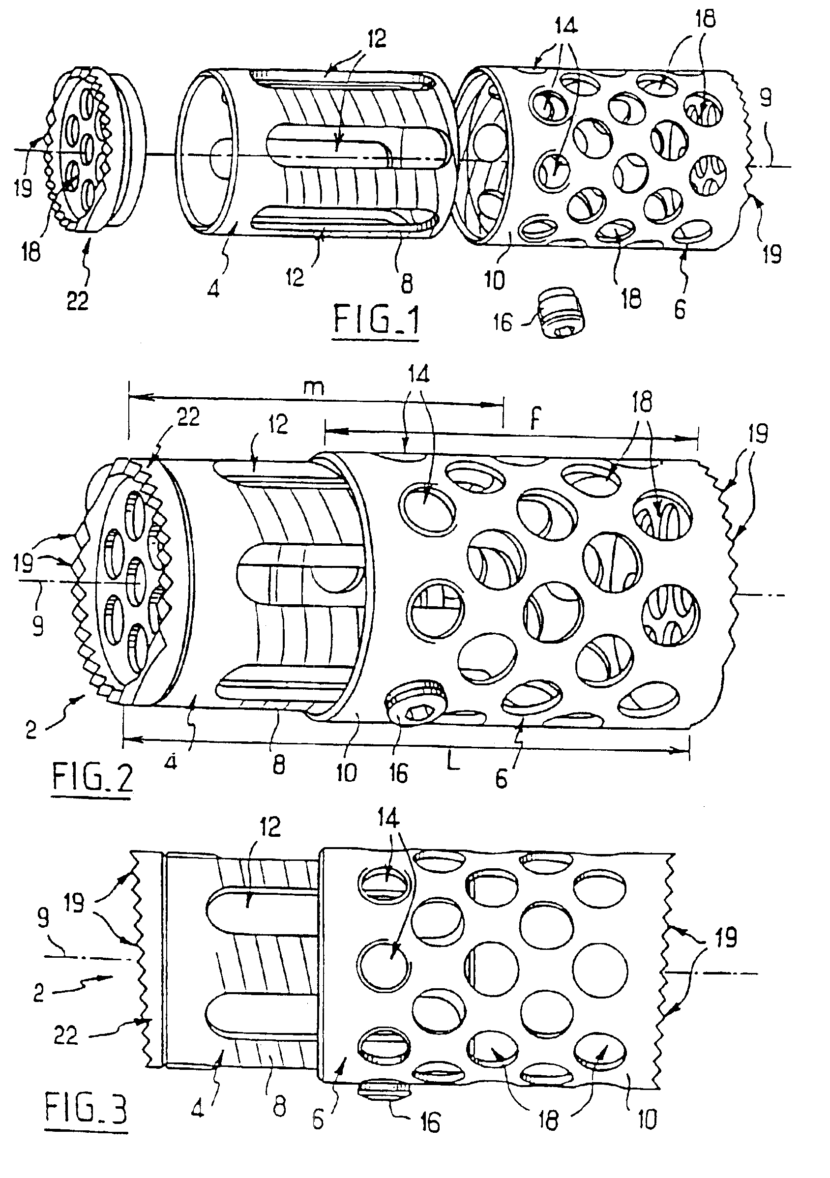
[0031]Referring to FIGS. 1 and 2, in the invention the implant 2 has two parts 4, 6.

[0032]Each part 4, 6 includes a cylindrical tubular one-piece body 8, 10 that has an axis 9. The body 8, also referred to as the male body, is adapted to penetrate into the body 10, also referred to as the female body, in a direction parallel to the axis 9. The male body 8 is threaded externally and the female body 10 is threaded internally to cooperate with the male body and provide a screw connection. A side wall of the male body 8 has identical rectilinear elongate openings or slots 12 of constant width that are parallel to each other and to the axis 9. Each extends more than half the length of the body 8 in a direction parallel to the axis 9. They are distributed all around that axis. A side wall of the female body 10 has a series of circular fixing openings or slots 14 that are identical to each other and lie in a common plane perpendicular to the axis 9 and in the vicinity of a proximal edge of...

second embodiment

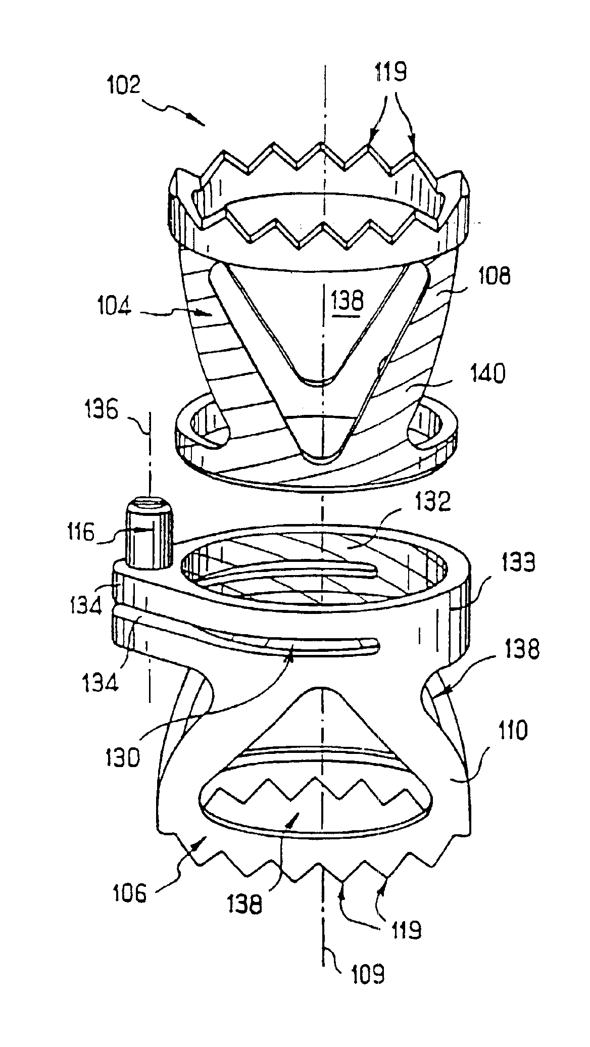
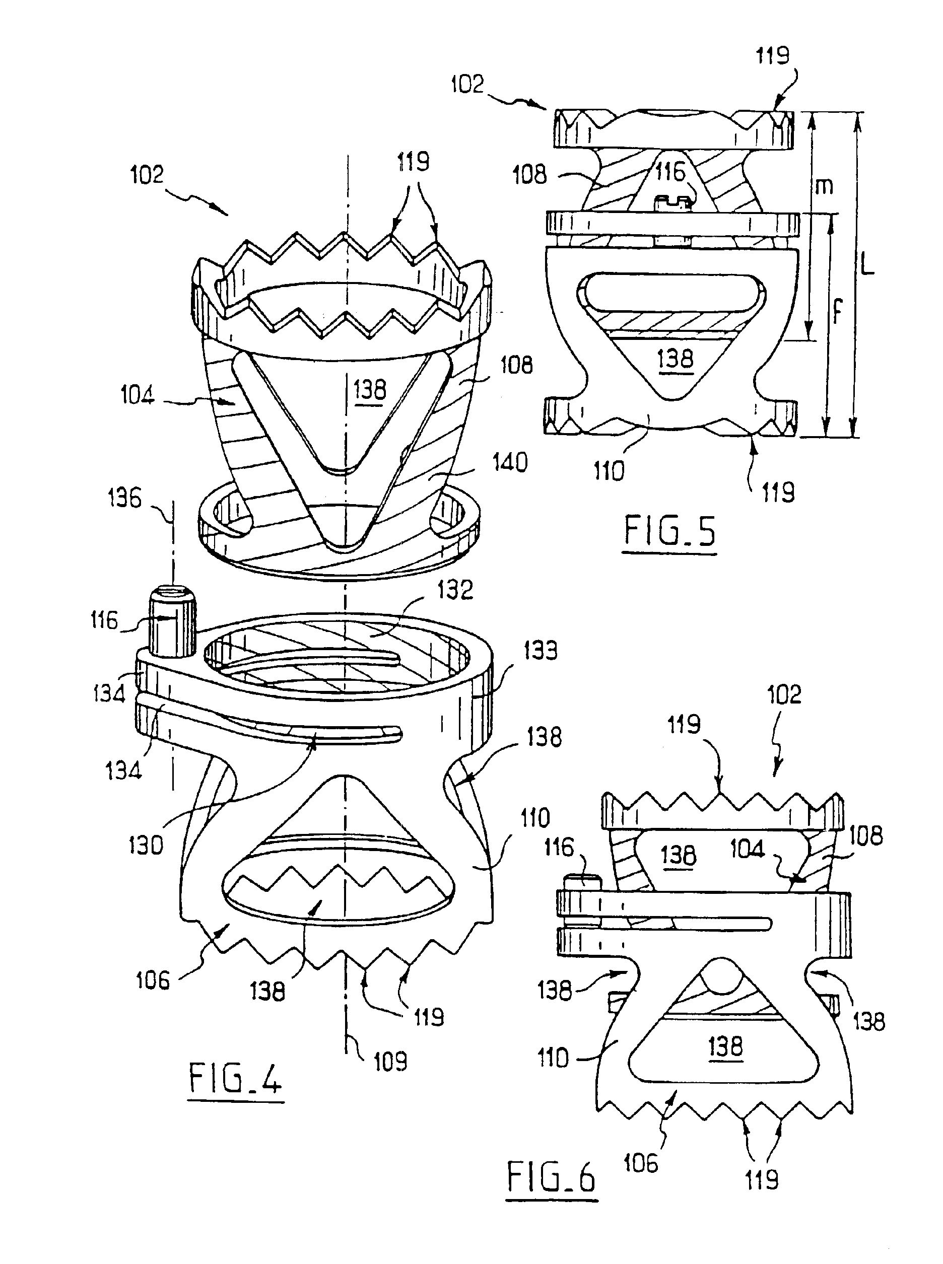
[0037]Referring to FIGS. 4 to 6, in the second embodiment, in which the reference numbers of corresponding components are increased by 100, the two parts 104, 106 of the implant provide a male-female coupling with a screw connection, as previously. Each distal edge and the teeth it carries are now in one piece with the corresponding body. The male part 104 is in one piece. The male part 104 and the female part 106 have no end walls and the ends of the implant associated with the distal edges are open.

[0038]The proximal edge of the female part 106 has a slot 130 in a plane perpendicular to the axis 109 and in the shape of a circular arc subtending an angle about the axis greater than 180°, for example equal to 200°. The slot 130 therefore delimits a flange 132 carrying the proximal edge and forming an uninterrupted circular collar which can move relative to the remainder of the body by elastic deformation of a junction part 133 connecting the remainder of the body to the flange. On e...


PUM


Abstract

The invention concerns an implant for replacing a vertebra at least partially, consisting of two parts adapted to be mutually connecting while enabling the adjustment of the implant total dimension, each part having an invariable dimension homologous with the implant dimensions. The parts form a screw-nut connection with each other.

Description

CROSS-REFERENCE TO RELATED APPLICATIONS[0001]The present application is a divisional of U.S. application Ser. No. 09 / 601,180 filed Sep. 15, 2000 now U.S. Pat. No. 6,616,695 is a national stage entry of PCT / FR99 / 00183 filed on Jan. 29, 1999.BACKGROUND OF THE INVENTION[0002]The invention relates to implants for replacing at least part of a vertebra, for example after ablation of the vertebra.[0003]The document EP-0 567 424-A1 discloses an implant of this kind comprising an intermediate body and two bearing parts adapted to bear against the vertebral plates of vertebrae adjacent the space left by a vertebra that has been removed. Each bearing part is assembled to one end of the intermediate body by a screw connection so that rotation of each bearing part relative to the body varies the total length of the implant. However, it takes a relatively long time to assemble the various components of the implant. What is more, given the number of parts capable of relative movement, adjusting th...

Claims


Application Information

Patent Timeline
Patent Type & Authority Patents(United States)
IPC IPC(8): A61F2/30A61F2/44A61F2/00A61F2/28
CPCA61F2/30744A61F2/4465A61F2/44A61F2230/0069A61F2002/2835A61F2002/30156A61F2002/30176A61F2002/30235A61F2002/30507A61F2002/3055A61F2002/30594A61F2002/30601A61F2002/30774A61F2002/30777A61F2002/30785A61F2002/30787A61F2002/30841A61F2002/4475A61F2220/0025A61F2230/0023A61F2230/0054A61F2002/30593
Inventor CROZET, YVESBACCELLI, CHRISTIAN
Owner STRYKER EURO OPERATIONS HLDG LLC
Why Eureka
Try Eureka