Fiber channel-inter changeable fiber optic connector

a fiber optic connector and fiber channel technology, applied in the field of fiber optic connector technology, can solve the problems of accidental damage of optical fiber core c1/b> of optical fiber core c, complicated interchanging operation of fiber channel, etc., and achieve the effect of quick interchange of fiber channels, saving molding and inventory costs, and being inexpensive to manufactur

Inactive Publication Date: 2014-05-20
CORNING OPTICAL COMM LLC
View PDF23 Cites 106 Cited by
  • Summary
  • Abstract
  • Description
  • Claims
  • Application Information

AI Technical Summary

Benefits of technology

[0011]The present invention has been accomplished under the circumstances in view. It is therefore the object of the present invention to provide a fiber channel-interchangeable fiber optic connector that allows quick interchange of fiber channels without dismounting the component parts. It is another object of the present invention to provide a fiber channel-interchangeable fiber optic connector, which is inexpensive to manufacture, saving much molding and inventory cost.
[0013]Based on the aforesaid arrangement, fiber channel interchange can be done conveniently by means of inserting a finger into the bottom locating hole and imparting an upward pressure to the springy hook at the bottom wall of the adapter to elastically deform the springy hook and then pulling the sub-assembly backwardly away from the adapter, and then respectively rotating the connectors and the sub-assembly relative to the adapter through 180-degrees angle, and then attaching the sub-assembly to the adapter again to force the springy hooks and the triangle stop blocks into engagement with the bottom locating hole, top locating hole and side holes of the sub-assembly respectively. This fiber channel interchanging operation is quite simple without dismounting the component parts.
[0014]The sub-assembly further comprises two guide grooves respectively disposed at opposing top and bottom sides in the accommodation chamber in communication with the bottom locating hole and the top locating hole for guiding the springy hooks of said adapter into engagement with the bottom locating hole and the top locating hole. The guide grooves in the accommodation chamber of the sub-assembly guide insertion of the springy hooks and triangle stop blocks of the adapter into position in the sub-assembly, facilitating quick installation of the sub-assembly with the adapter.
[0015]Further, when the sub-assembly is attached to the adapter, the respective end edges of the side holes of the sub-assembly are respectively stopped against respective vertical stop faces of the triangle stop blocks to prohibit forward displacement of the sub-assembly relative to the adapter, and the bottom locating hole of the sub-assembly is engaged with the springy hook at the bottom wall of the adapter to stop the sub-assembly from backward displacement relative to the adapter.
[0017]Further, the adapter consists of a first adapter shell member and a second adapter shell member. The first adapter shell member and second adapter shell member of the adapter are identical but set in different directions. By means of plugging a locating pin of one of the first adapter shell member and the second adapter shell member into a pinhole of the other of the first adapter shell member and the second adapter shell member, a hook and a hook hole of the first adapter shell member are respectively forced into engagement with a hook hole and a hook of the second adapter shell member, and therefore the first adapter shell member and the second adapter shell member are fastened together. As the first adapter shell member and the second adapter shell member are identical, the invention saves the molding and inventory cost.

Problems solved by technology

Under the strong demand for network data transmission, conventional cable transmission techniques cannot satisfy the various needs.
This fiber channel interchanging operation is complicated and requires a special hand tool.
When interchanging the two connectors B, the optical-fiber cores C1 of the optical cable C may be damaged accidentally.

Method used


Image

  • Fiber channel-inter changeable fiber optic connector
  • Fiber channel-inter changeable fiber optic connector
  • Fiber channel-inter changeable fiber optic connector

Examples


Embodiment Construction

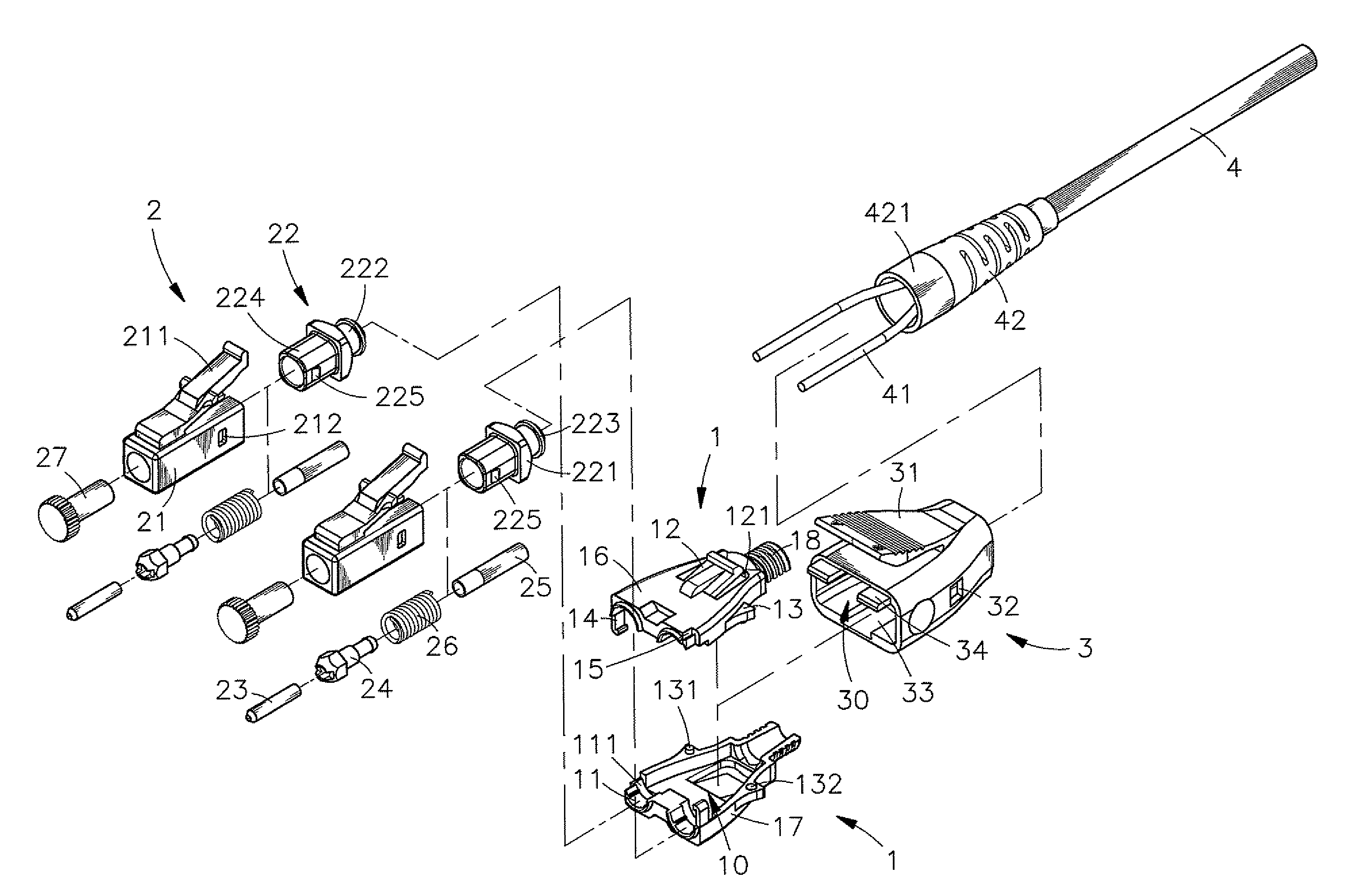
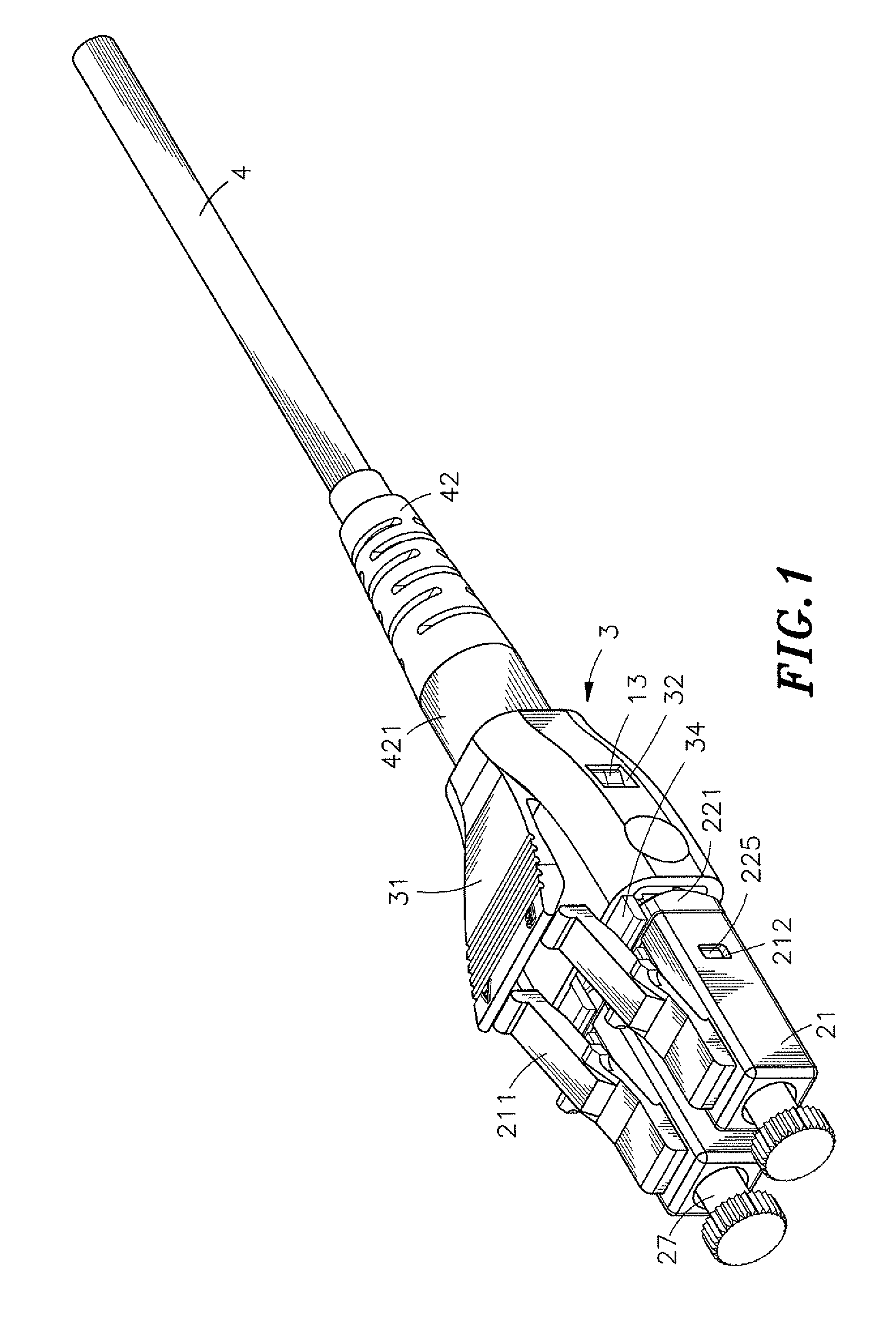
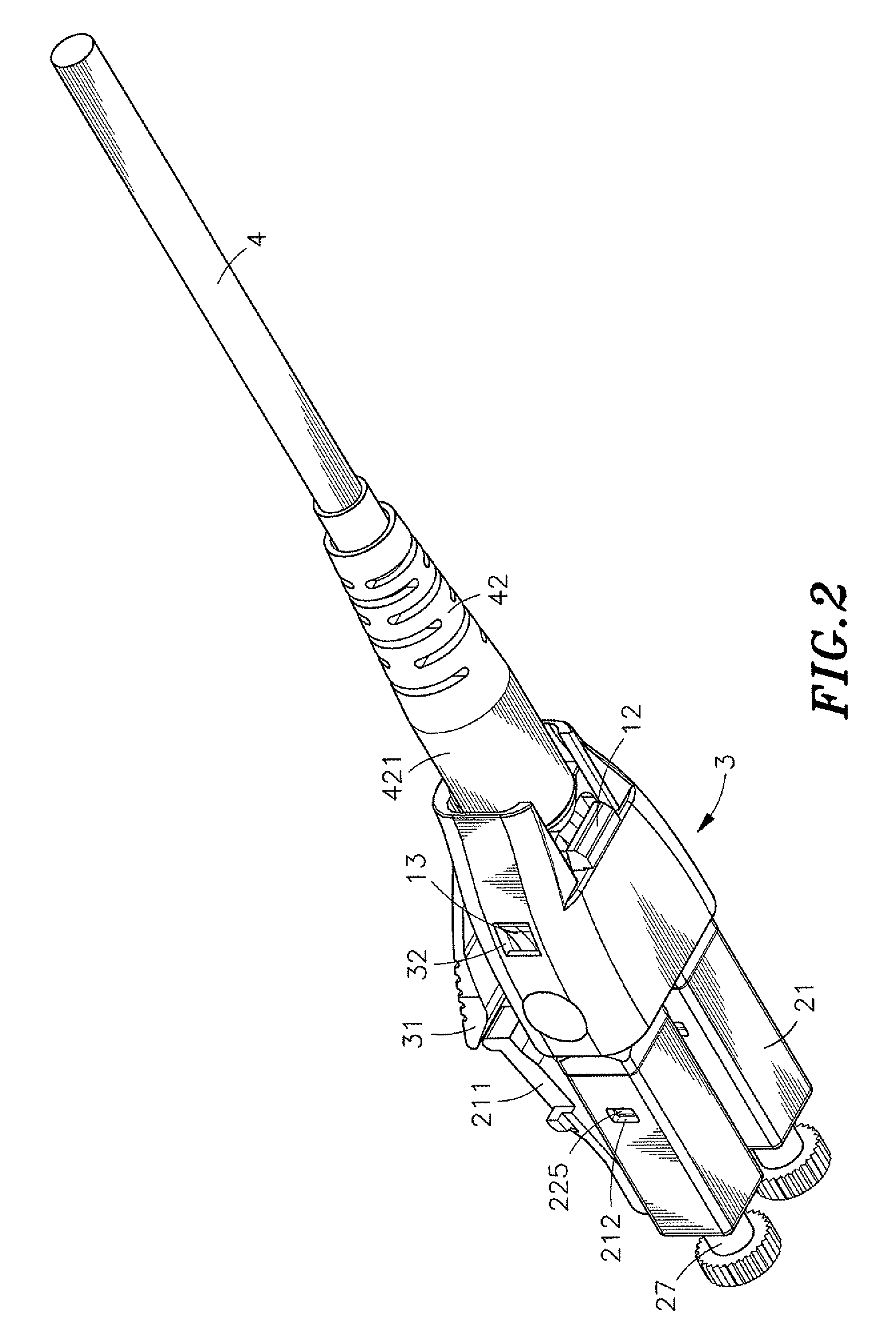
[0029]Referring to FIGS. 1-5, a fiber channel-interchangeable fiber optic connector in accordance with the present invention is shown comprising an adapter 1, two connectors 2, a sub-assembly 3 and a cable 4.

[0030]The adapter 1 is an electrically insulative hollow shell having a width gradually reduced from the front side toward the rear side. The adapter 1 comprises an inside accommodation chamber 10, two axle holes 11 located on the front side thereof in a parallel manner and axially disposed in communication with the inside accommodation chamber 10, two annular locating grooves 111 respectively extending around the respective inner ends of the axle holes 11 and kept in communication with the inside accommodation chamber 10 and having a diameter greater than the axle holes 11, two springy hooks 12 respectively and obliquely backwardly extended from opposing top and bottom walls thereof, two triangle stop blocks 13 respectively located on opposing left and right sidewalls thereof, ...


PUM


Abstract

A fiber channel-interchangeable fiber optic connector includes an adapter, two connectors respectively rotatably mounted in respective axle holes at the front side of the adapter, a sub-assembly detachably attached to the adapter to stop the connectors from rotation and hold down the connectors in position, and a cable inserted through the sub-assembly and mounted in the adapter with two optical-fiber cores therein respectively inserted into ferrules of the connectors. Detaching the sub-assembly from the adapter allows rotation of the connectors and the sub-assembly through 180-degrees angle relative to the adapter to interchange the fiber channels.

Description

BACKGROUND OF THE INVENTION[0001]1. Field of the Invention[0002]The present invention relates to fiber optic connector technology and more particularly, to a fiber channel-interchangeable fiber optic connector that allows quick interchange of fiber channels without dismounting the component parts.[0003]2. Description of the Related Art[0004]With the development and maturity of network technology, network data transmission requirements keep increasing. Under the strong demand for network data transmission, conventional cable transmission techniques cannot satisfy the various needs. Nowadays, fiber optic transmission technology has been intensively used for network data transmission applications for the advantages of high transmission speed, large data transmission capacity and accurate data transmission. In consequence, many different fiber optic connectors have been created for linking of fiber optic cables or fiber optic testing to widen fiber optic application range and to enhance...

Claims


Application Information

Patent Timeline
Patent Type & Authority Patents(United States)
IPC IPC(8): G02B6/36
CPCG02B6/3879G02B6/3887
Inventor LEE, JHIH-PINGHSU, KUO-FU
Owner CORNING OPTICAL COMM LLC
Why Eureka
Try Eureka