Interchangeable button system technology

a button system and interchangeable technology, applied in the field of interchangeable button systems, can solve the problems of time-consuming and fabric-deterioration tasks, the problem of not being able to solve the problems in combination or without the use of special tools, and the difficulty of sewing a button correctly onto a shirt. to achieve the effect of quick interchangeability

Active Publication Date: 2019-10-29
MARIN ANIBAL
View PDF56 Cites 10 Cited by
  • Summary
  • Abstract
  • Description
  • Claims
  • Application Information

AI Technical Summary

Benefits of technology

[0018]In an embodiment of the present invention, an interchangeable button system with a fastener is provided which is decorative, universal, and quickly interchangeable for a variety of products without the need of sewing.
[0019]The interchangeable button assembly system may include a pronged fastener that penetrates a material coupling to a button base. The pronged fastener and button base become permanently affixed to the material allowing mating with an interchangeable button cap until securely tightened. Embossed designs on the rear of pronged fastener base provide grip creating maximum torquing stability when interchanging button caps. The interchangeable button cap can be replaced indefinitely, changing the appearance and function of a button quickly.

Problems solved by technology

It is a very time consuming and fabric-deteriorating task to change the appearance of the buttons which are sewn on garments and accessories.
For those who have no knowledge of sewing or users with visual impairment, sewing a button correctly onto a shirt can be extremely difficult.
However, none of these solutions seemed to have solved the problems in combination or without the use of special tools, creating disadvantages.
The pronged fasteners limit flexibility and ergonomic maneuverability for closure of dual layered fabrics, smaller buttons and tighter button holes.
However, the head and button body limits the coverage options of the interchanging heads and requires a special drive pin along with a locking plate making it a complex task.
This arrangement causes severe wear to the punctured area weakening the fabric over time.
In addition, the nut is only stationary when used in conjunction with the threaded shank, creating the possibility of losing either piece when not in use.
Furthermore, this process of application is unfavorable for current day manufacturing.
In Burgio, U.S. Pat. No. 3,725,980, the entire structure is difficult to dismember and creates the potential for losing all the parts.
This process is time consuming and if done improperly can leave undesired results.
The stud method of sewing is less desirable, not used in a majority of applications and is more susceptible to breaking with a constantly interchanging cover.
As a consequence of this slide-on arrangement, seams caused by the joining of the button cover and base, lead to an unpleasant and non-conventional button aesthetic.
In addition, the smaller the button, the more difficult it would be to accurately register the two parts.
Initially registering the flanges to align the interrupted threads is time consuming and can lead to misregistration of the helical thread.
Interrupted helical threads are difficult to manufacture and are much easier to damage with constant twisting.
In addition, if the cap part is lost, the edges of the interrupted threads can damage fabric and button holes.
This can cause extreme wear if fastened by thread.
Initially registering the base flaps to the cap notches is time consuming, specifically if the base is attached by thread creating an unstable platform.
In addition, if the cap part is lost, the edges of the base flaps can damage fabric and button holes.
Both processes are time consuming and if done improperly can leave undesired results or change the full appearance of the button.
This fastening system couples onto itself independently from any button and is susceptible to greater movement and strain.
It is specifically inadequate for an interchangeable button system that is constantly pressured, pulled and torqued in non-standard button requirements.
In addition there is high material wastage by discarding the gripping members leading to an inefficient and non-sustainable product for manufacturing.
This particular configuration can be frustrating to register and provides no backing to the u-shaped barbed loop for maximum compression.
An additional disadvantage is that the barbed loop is relatively difficult to handle due to the fact that the parts must be relatively small.
The prior art does not provide a button system with both interchangeability and fastening which is closest in appearance to, functionality of and ease of use to conventional buttons.

Method used


Image

  • Interchangeable button system technology
  • Interchangeable button system technology
  • Interchangeable button system technology

Examples


first embodiment

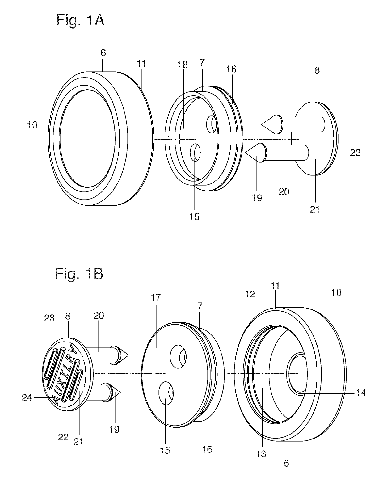
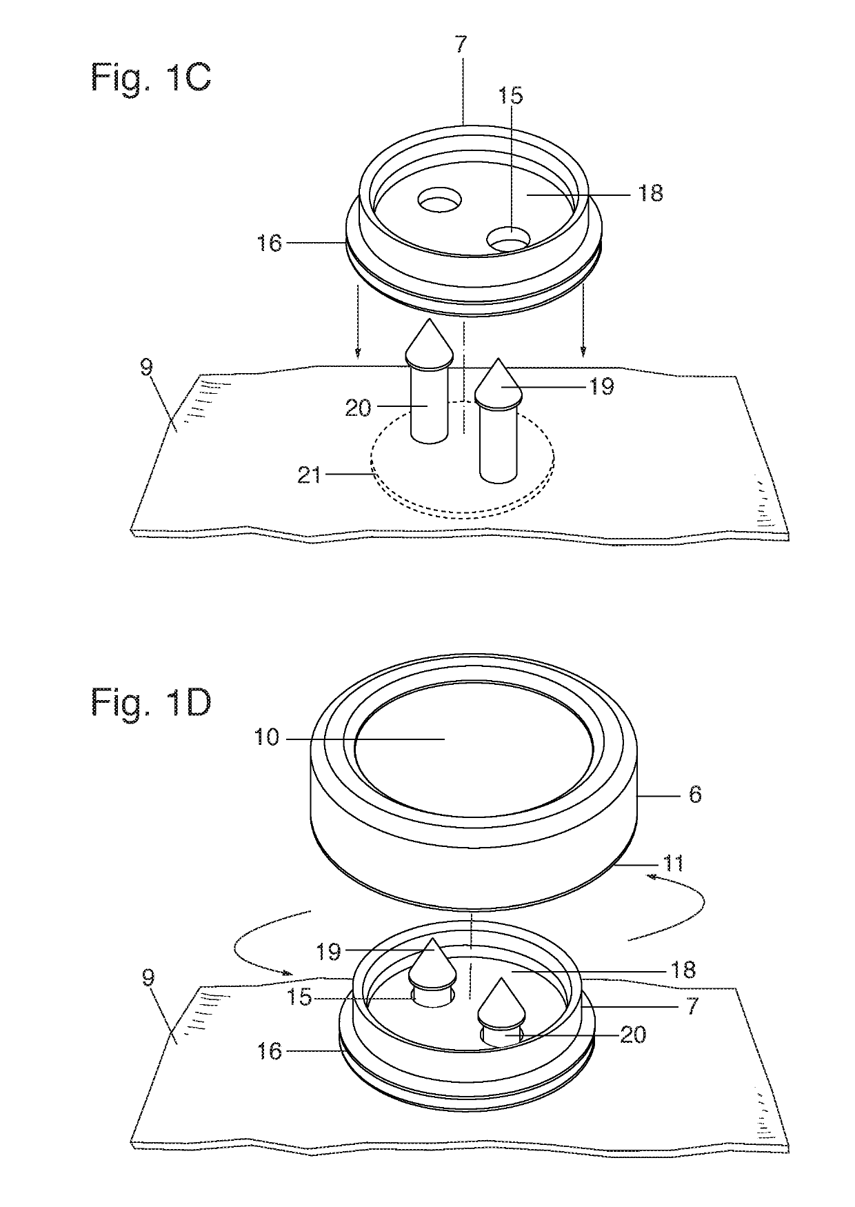
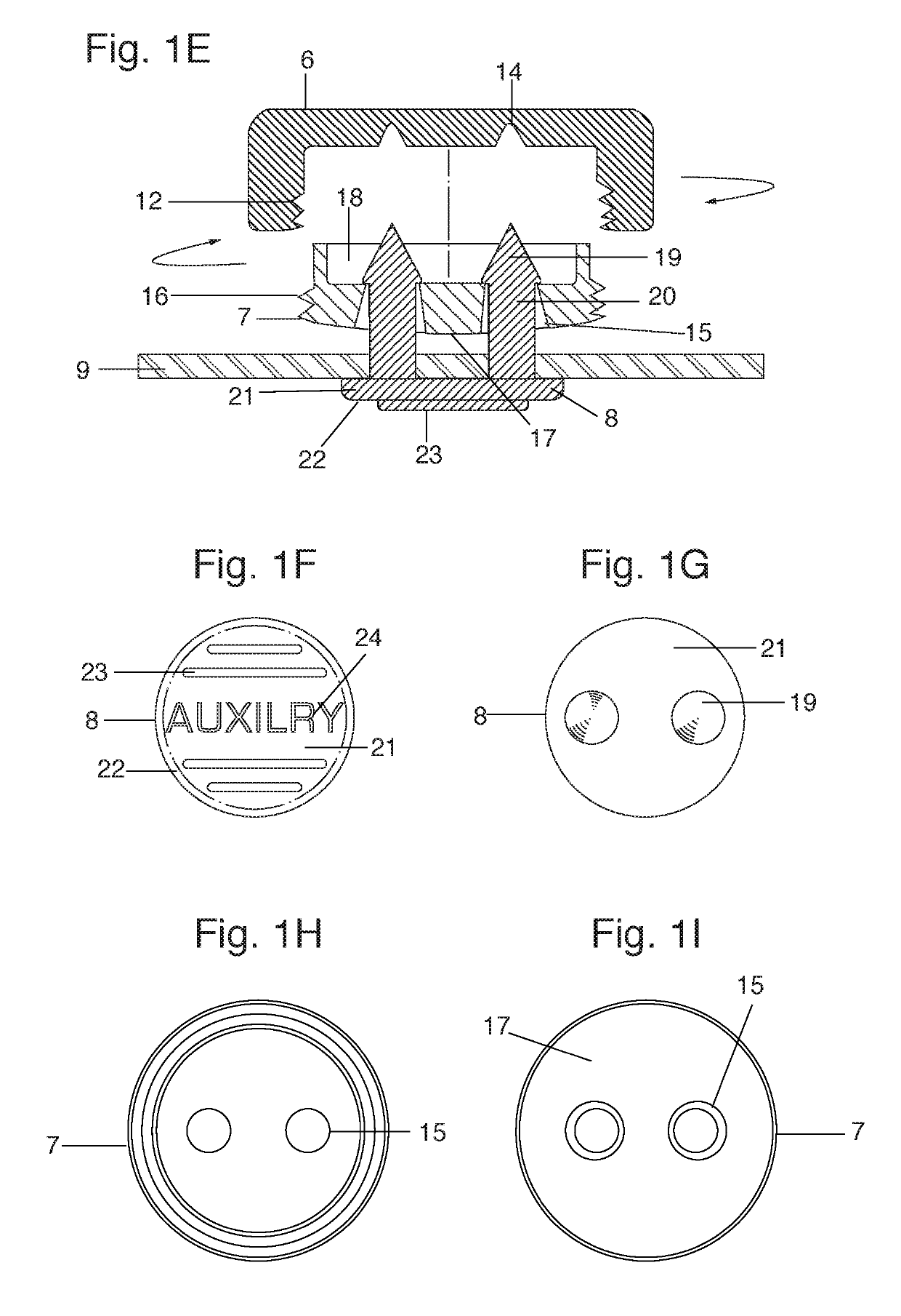
[0047]FIGS. 1A-1K shows an interchangeable button system of the present invention. The interchangeable button system has an interchangeable cap 6, a base button 7 and a pronged fastener 8.

[0048]The interchangeable cap 6 is the main visible part of a button assembly that registers with an external base thread 16 on base button 7, interlocking the two parts. The interchangeable cap 6 is the main visible part of a button assembly that allows a user a wide selection of different designs, materials and / or functions. Although interchangeable cap 6 shown in the preferred embodiment is relatively simple in design, its appearance can greatly be varied without departing from the teachings of the present invention. For example, interchangeable cap 6 can be contoured to replicate a traditional sewn on button design for fashion purposes. Similarly, interchangeable cap face 10 can be coated with reflective material for use as a removable safety function in hazardous situations. Interchangeable ca...

second embodiment

[0057]FIG. 2C is a lateral cross-sectional view of the present invention with the interchangeable cap 6 and button base 7 attached to fabric 9 by prong fastener 8. The interchangeable cap 6 and locking pin or protrusion 26 are tightened and secured to button base 7. Further shown are arrows indicating the rotational tightening motion of interchangeable cap 6 in synchronization with the projected path of locking pin 26 along helical track 25. The locking position of the interchangeable cap 6 is achieved when locking pin 26 slides along edge of helical track 25 registering into locking groove 34 (also seen in FIG. 2B). It should be noted that that the prongs tips 19 are not shown in this figure for clarity purposes.

third embodiment

[0058]FIG. 3A-3C shows an interchangeable button system of a

[0059]In this embodiment, a cap member 27 of the interchangeable cap 6 has a chamfered flange 28 with non-slip teeth 30. Non-slip teeth 30 are used in combination with interchangeable cap 6 to prevent internal spinning of cap member 27 from excessive torque or constant interchange use. The cap member 27 also has internal cap member threads 29 that securely fastens counterpart internal cap thread 12 on base button 7.

[0060]The interchangeable button system of the third embodiment may be used when various materials are to be used for interchangeable cap 6 that are different from cap member 27.


PUM


Abstract

A interchangeable button system that has an interchangeable cap, a base button and a pronged fastener allowing the user to change the appearance and functionality of buttons, quickly and conveniently without sewing. The pronged fastener penetrates fabric exposing the prong tips for alignment with the base buttonholes located on the base button. Compression on the base button couples the pronged fastener with the base buttonholes creating a secure permanent attachment. The base button has an external base thread that aligns with internal cap thread for coupling. Thus the interchangeable cap can be torqued on or off. Different functional decorative and technological types of interchangeable caps may be selectively torqued onto base button for end use.

Description

BACKGROUND OF THE INVENTION[0001]Field of the Invention[0002]The invention pertains to the field of clothing and accessory buttons. More particularly, the invention pertains to an interchangeable button system that attaches with a fastener replacing the sewing operation and allowing the facing of the button to be changed quickly, serving decorative or utility functions.[0003]Description of Related Art[0004]It is a very time consuming and fabric-deteriorating task to change the appearance of the buttons which are sewn on garments and accessories. On average, the changing of sewn-on buttons on a garment or accessory occurs once during the lifetime of the garment or accessory, and is mainly for repair purposes. For those who have no knowledge of sewing or users with visual impairment, sewing a button correctly onto a shirt can be extremely difficult.[0005]Therefore, replacing the aesthetic or function of sewn on buttons without the sewing operation to compliment or enhance a garment or...

Claims


Application Information

Patent Timeline
Patent Type & Authority Patents(United States)
IPC IPC(8): A44B1/14A44B1/34
CPCA44B1/14A44B1/34
Inventor MARIN, ANIBAL
Owner MARIN ANIBAL
Why Eureka
Try Eureka