Systems and methods for manufacturing a pre-charge circuit module

a pre-charge circuit and module technology, applied in the direction of printed circuit board receptacles, electrical apparatus construction details, support structure mounting, etc., can solve the problems of difficult replacement of pre-charge device components, inefficient use of space, and variable adverse effects of motor drives, so as to efficiently access the pre-charge circuit and quickly interchange components

Active Publication Date: 2015-05-07
ROCKWELL AUTOMATION TECH
View PDF8 Cites 11 Cited by
  • Summary
  • Abstract
  • Description
  • Claims
  • Application Information

AI Technical Summary

Benefits of technology

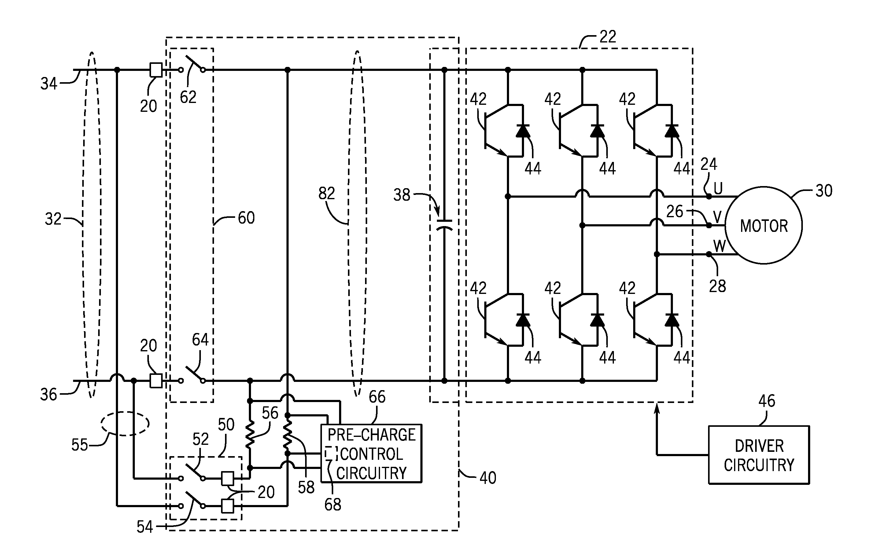
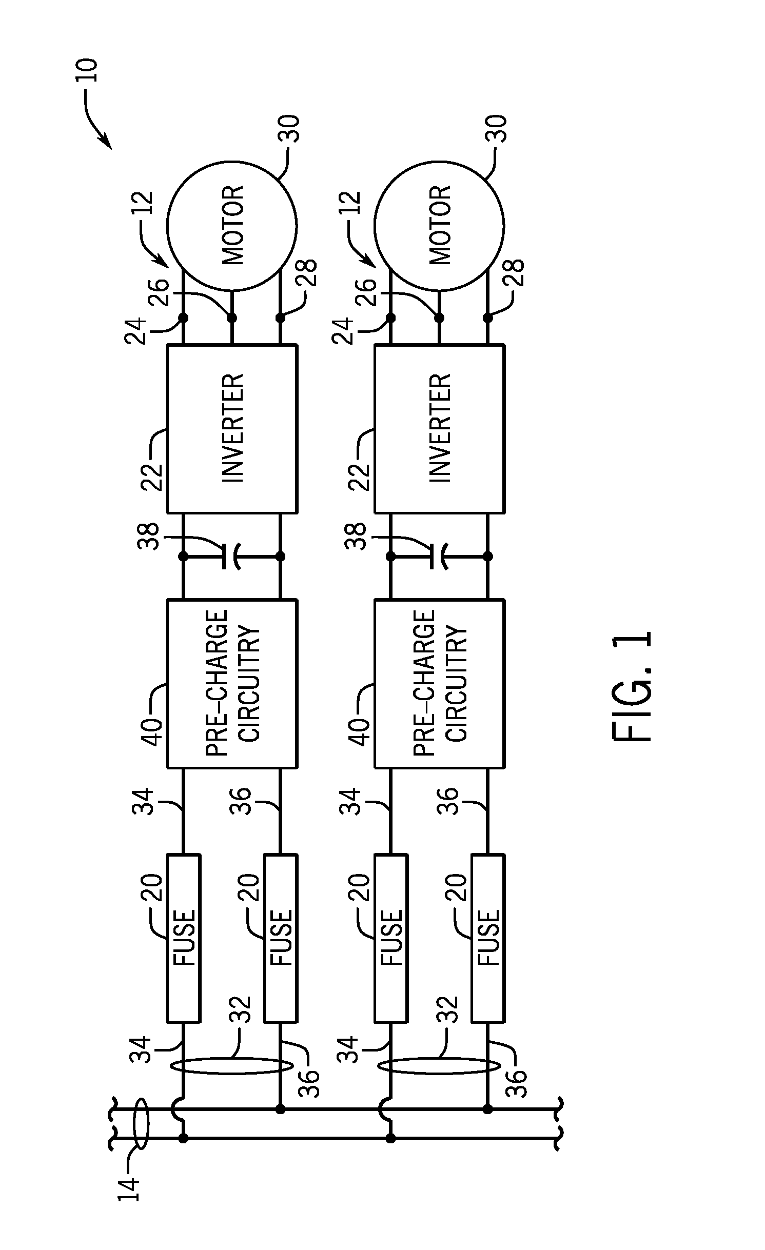
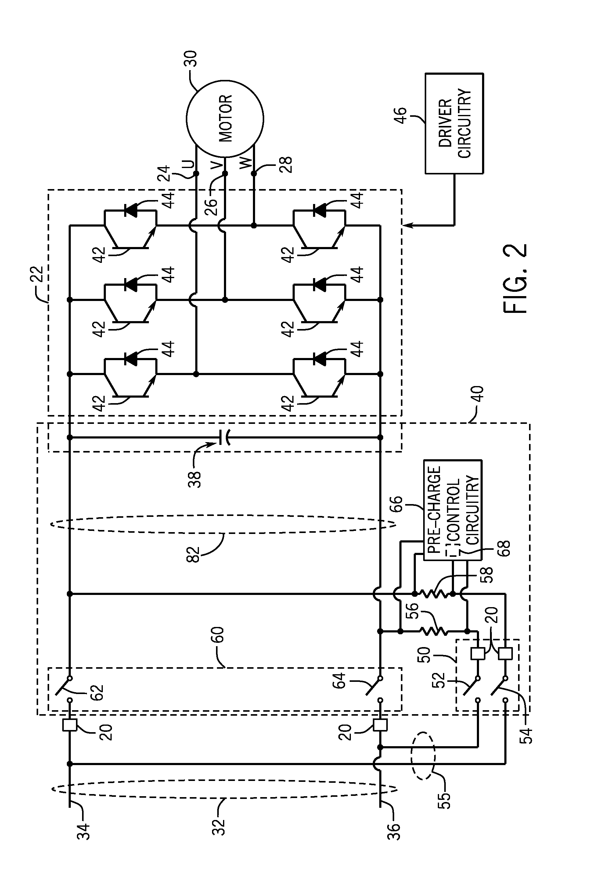
[0006]The present disclosure relates generally to a systems and methods for manufacturing a pre-charge circuit for pre-charging a DC bus of a motor drive system. Specifically, the pre-charge circuit may be a modular structure that may couple the pre-charge circuit to an inverter module, such that the pre-charge circuit module and the inverter module may be enclosed within the same power cabinet. Moreover, by using a modular structure to house the pre-charge circuit, a user may more efficiently access the pre-charge circuit for service or may quickly interchange an entire module for various reasons.

Problems solved by technology

The high levels of in-rush current may cause various adverse effects to the motor drive.
Mounting the components on a flat array, however, may not be an efficient use of space.
Moreover, mounting the components in this manner may also make replacing components of the pre-charge device challenging.

Method used


Image

  • Systems and methods for manufacturing a pre-charge circuit module
  • Systems and methods for manufacturing a pre-charge circuit module
  • Systems and methods for manufacturing a pre-charge circuit module

Examples


Embodiment Construction

[0022]One or more specific embodiments will be described below. In an effort to provide a concise description of these embodiments, not all features of an actual implementation are described in the specification. It should be appreciated that in the development of any such actual implementation, as in any engineering or design project, numerous implementation-specific decisions must be made to achieve the developers' specific goals, such as compliance with system-related and business-related constraints, which may vary from one implementation to another. Moreover, it should be appreciated that such a development effort might be complex and time consuming, but would nevertheless be a routine undertaking of design, fabrication, and manufacture for those of ordinary skill having the benefit of this disclosure.

[0023]When introducing elements of various embodiments of the present invention, the articles “a,”“an,”“the,” and “said” are intended to mean that there are one or more of the ele...


PUM

PropertyMeasurementUnit
voltage ratingaaaaaaaaaa
DC poweraaaaaaaaaa

Abstract

Systems, methods, and devices are provided for coupling a direct current (DC) pre-charging circuit to a motor drive. In one embodiment, an industrial automation device may include an enclosed module that may include a pre-charge circuit. The pre-charge circuit may pre-charge a direct current (DC) bus. Further, the DC bus may couple to an inverter. The enclosed module may also include a power input that may couple the pre-charge circuit to a DC power source and an electrical output structure that may couple the pre-charge circuit to the inverter. Additionally, the pre-charge circuit may be removeably coupled to the inverter and the DC power source via a sliding action of the enclosed module.

Description

BACKGROUND[0001]The present disclosure relates generally to the field of electrical drives. More particularly, the present disclosure relates to a modular embodiment of a pre-charge circuit for pre-charging a direct current (DC) bus in a power electronic device, such as an electrical drive.[0002]In the field of power electronic devices, a wide range of circuitry is known and currently available for converting, producing, and applying power to loads. Depending upon the application, motor drive systems may include circuitry that converts incoming power from one form to another as used by the load. In a typical drive system, for example, a rectifier converts alternating current (AC) power (such as from a utility grid or generator) to direct current (DC) power. Inverter circuitry can then convert the DC power into a controllable AC power having a particular frequency for driving a motor at a particular speed. The inverter circuitry typically includes several high power switches, such as...

Claims


Application Information

Patent Timeline
Patent Type & Authority Applications(United States)
IPC IPC(8): H02M7/5387H05K13/00
CPCH05K13/00H02M7/5387Y10T29/49117H05K7/14327H05K7/1432
Inventor KEEGAN, JEREMY JONPATEL, YOGESHWEISS, BRUCE WILLIAMCARTER, JAMES ALLEN
Owner ROCKWELL AUTOMATION TECH
Why Eureka
Try Eureka