Clamping fixture with adjustable assemblies

a technology of fixing fixture and assembly, which is applied in the direction of positioning apparatus, metal-working machine components, manufacturing tools, etc., can solve the problems of damage to the table, scratches and divots, and excessive surface wear, and achieve the effect of quick replacemen

Active Publication Date: 2012-02-14
KELL TECH
View PDF10 Cites 10 Cited by
  • Summary
  • Abstract
  • Description
  • Claims
  • Application Information

AI Technical Summary

Benefits of technology

[0011]According to an aspect of the invention, the work piece holder includes a first adjustable spacer assembly, and first and second jaw assemblies engaging the base. The first adjustable spacer assembly includes a spacer disposed between the work piece holder and the base for locally adjusting the spacing therebetween, a first head, a first threaded portion and a second threaded portion. The first head is coupled to the first threaded portion and the first adjustable spacer is coupled to the second threaded portion. The first threaded portion and the second threaded portion are each threaded in the same direction and preferably have different pitches. When the first adjustable spacer travels along the second threaded portion, the work piece holder is adjustable along an incline relative to the base. The first and second base-engaging jaw assemblies each include a base-engaging jaw disposed between the work piece holder and the undercut edge for locally adjusting the spacing between the work piece holder and the base. Each base-engaging jaw assembly also includes a first head, a first threaded portion and a second threaded portion. The first head of each assembly is coupled to the first threaded portion of each assembly and the base-engaging jaw of each assembly is coupled to the second threaded portion of each assembly wherein the first threaded portion and the second threaded portion are each threaded in the same direction and preferably have different pitches. When the first base-engaging jaw travels along the second threaded portion of the first base-engaging jaw assembly, the work piece holder is adjustable along an incline relative to the base. When the second base-engaging jaw travels along the second threaded portion of the second base-engaging jaw assembly, the work piece holder is horizontally translated relative to the base. Thus, the work piece holder can be easily adjusted relative to the base at multiple angles.
[0014]Another object of the invention is to provide a fixture that allows the fixture to be finely adjusted at various angles.
[0016]Yet, another object of the invention is to provide a fixture which has attachments that can be interchanged quickly.

Problems solved by technology

A problem with these systems is that laying the leveling head directly on the machine support surface causes excessive wear to the surface.
For example, placing and removing the leveling head on and from an E.D.M. table, made of soft stainless steel, often causes scratches and divots, or otherwise damages the table.
Since a damaged table can lead to imprecision, even damage appearing minor can nonetheless generate the need to replace the support surface.
Another problem with the leveling head being mounted directly on the support surface of a machine tool is that a limited number of directional adjustments can be made to the device.
Further, it is inconvenient to attach and remove the clamping device from the machine tool as an Allen wrench or other tool is usually required to attach a releasing lever before the device can be removed.
Yet another problem is that the systems are expensive and so bulky that the machine tool does not have the capacity to accommodate a stack of clamping devices to provide additional clamping support.

Method used


Image

  • Clamping fixture with adjustable assemblies
  • Clamping fixture with adjustable assemblies
  • Clamping fixture with adjustable assemblies

Examples


Embodiment Construction

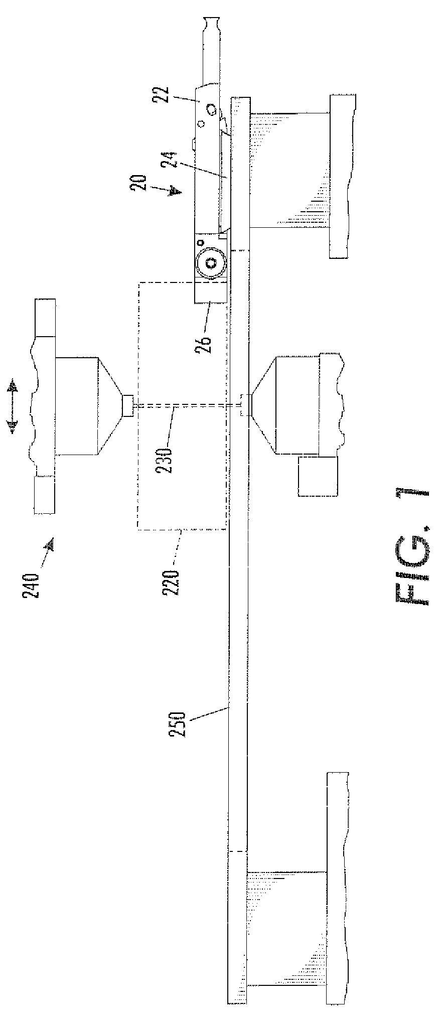
[0027]Referring to the Figures, FIG. 1 is a side view of an embodiment of the present invention showing a fixture 20 holding a work piece 220 being cut by a wire 230 of a machining workstation 240 such as an E.D.M tool. The fixture 20 includes a work piece holder 22 that engages a base 24 attachable to a support surface 250, such as a wire E.D.M table surface. As shown in the figure, the work piece 220 can be held by moveable work piece attaching jaws 26 such as a clamp.

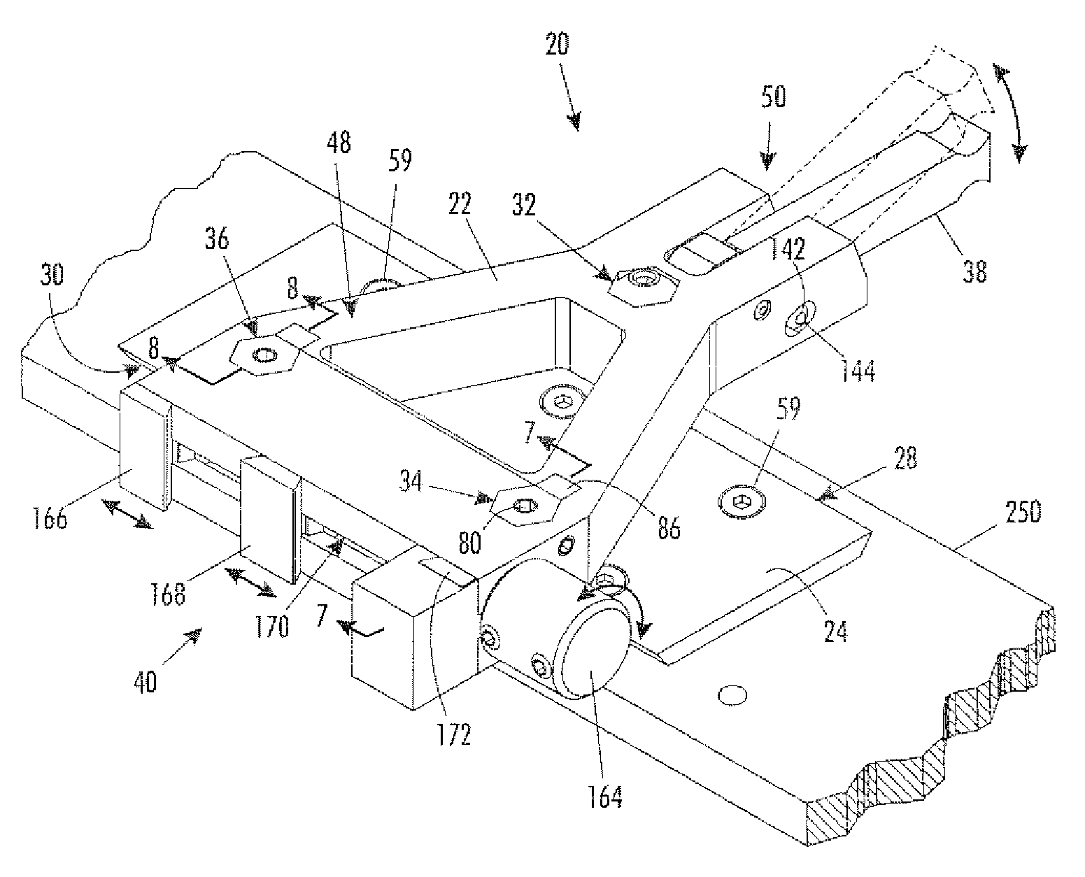
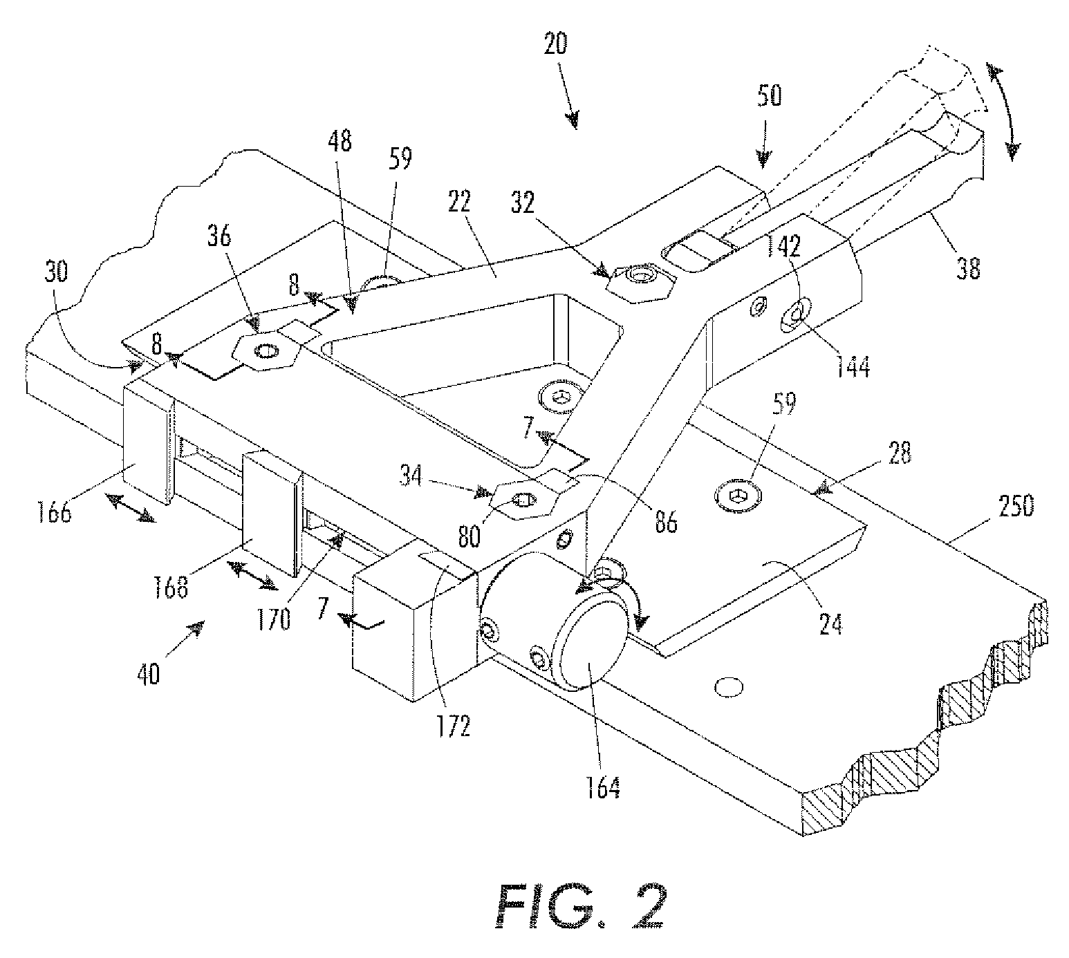
[0028]FIGS. 2, 3 and 4 are additional views of the work piece holder 22 engaging undercut portions 28, 30 of the base 24 The work piece holder 22 includes an adjustable spacer assembly 32, two base-engaging jaw assemblies 34, 36 a release lever 38 and a work piece clamping region 40. The adjustable spacer assembly 32 includes a spacer 42 and the two base-engaging jaw assemblies 34, 36 include a first base-engaging jaw 44 and a second jaw 46 as shown in FIGS. 7 and 8 and as discussed in more detail infra. The two base...


PUM


Abstract

The present invention includes a fixture for securing a work piece to a support surface at a machining workstation comprising a base attachable to the support surface and having at least one undercut edge, and, a work piece holder engaging the at least one undercut edge of the base, spaced apart from the support surface, and having moveable work piece attaching jaws.

Description

CROSS-REFERENCE TO RELATED APPLICATIONS[0001]Not applicable.STATEMENT REGARDING FEDERALLY SPONSORED RESEARCH OR DEVELOPMENT[0002]Not applicable.REFERENCE TO A “SEQUENCE LISTING”[0003]None.TECHNICAL FIELD[0004]This invention relates generally to fixtures for a supporting surface of a machining workstation, and more specifically to a clamping fixture for a wire E.D.M. (Electrical Discharge Machine), wherein the fixture includes a work piece holder coupled to a base.BACKGROUND OF THE INVENTION[0005]A wire E.D.M. is used by manufacturers to make precision cuts in work pieces. To provide optimal cutting results, it is necessary to secure firmly and orient each work piece being cut. Various clamping systems are used in precision machinery to releasably secure and orient a work piece.[0006]Typically, the clamping systems include a leveling head having a clamping portion for securing a work piece and a base portion for securing the clamping device to a support surface. The clamping device i...

Claims


Application Information

Patent Timeline
Patent Type & Authority Patents(United States)
IPC IPC(8): B25B1/20
CPCB23Q3/06B23Q3/103
Inventor KELLERSON, KENNETH W.
Owner KELL TECH
Why Eureka
Try Eureka