Device for converting solar radiation into electric power

a technology for solar radiation and electric power, applied in the direction of photovoltaic modules or panels installed on the roofs of buildings, moving/orienting solar heat collectors, etc., can solve the problems of reducing the yield of the device, the cost of the known types of device for converting solar radiation into electric power is still rather high, and the installation of the photovoltaic module or panel on the roof cannot be performed in a manner that provides the best conditions of performan

Inactive Publication Date: 2005-08-16
MATTIUZZO GILBERTO
View PDF15 Cites 104 Cited by
  • Summary
  • Abstract
  • Description
  • Claims
  • Application Information

AI Technical Summary

Benefits of technology

[0019]The aim of the present invention is therefore to solve the noted technical problems, eliminating the drawbacks of the cited known art and thus providing an invention that allows to provide optimum collection of solar radiation and its conversion into electric power, regardless of the orientation of the home or of the user device intended to utilize said electric current.

Problems solved by technology

The main disadvantage of this constructive solution is that, quite often, installation of the photovoltaic modules or panels on the roofs of buildings cannot be performed in a manner that provides the best conditions of performance.
This drawback entails a net loss of the quantity of irradiation, which leads to a reduced yield of the device.
Since the cost of the known types of device for converting solar radiation into electric power is currently still rather high and entails very long plant amortization times, a sharp loss in performance, possibly as high as 50%, leads to a drastic increase in amortization times or worse still to the choice not to purchase this kind of device.
Another drawback of known types of device relates to the fact that at certain times of day the roof of the building can be covered by shadows cast by taller nearby buildings, and this also causes a loss of performance.
The drawbacks of this solution are the same ones noted above, since by being arranged generally vertically their orientation is in any case not the optimum one and the possibility of being covered by shadows is even greater because of the fact that they are at a lower height from the ground.
One drawback of this constructive solution consists of the fact that said panels or modules, which necessarily have a large surface of exposure to the sun, constitute a considerable bulk and space occupation at the ground where they are located.
Another drawback is the fact that they are even more subject to be covered by shadows cast by trees or other buildings, since they are located almost at ground level.
Another problem of these known types is the fact that they can be accessed easily by anyone, and this can entail a risk due to their possible damage or even their theft.

Method used


Image

  • Device for converting solar radiation into electric power
  • Device for converting solar radiation into electric power
  • Device for converting solar radiation into electric power

Examples


Embodiment Construction

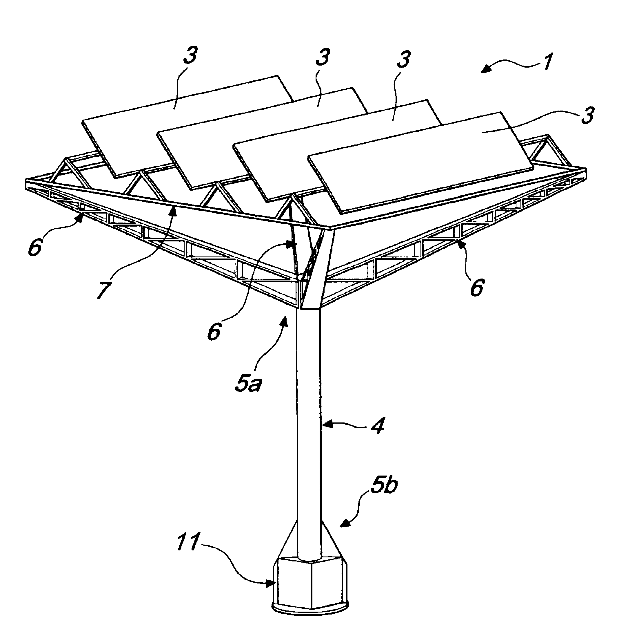
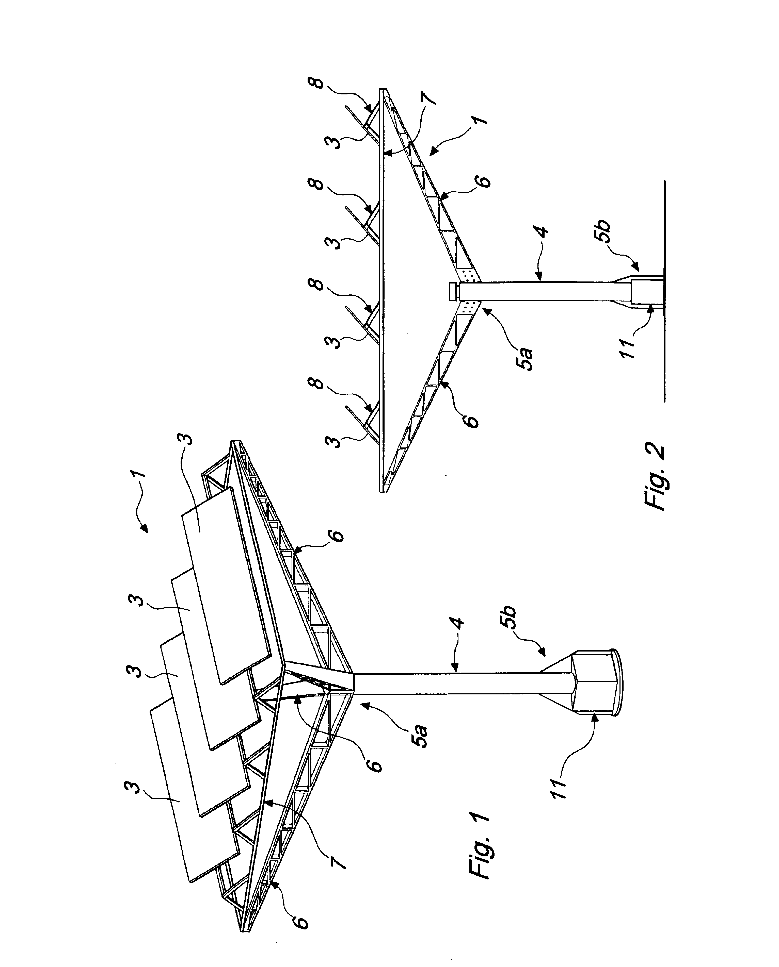
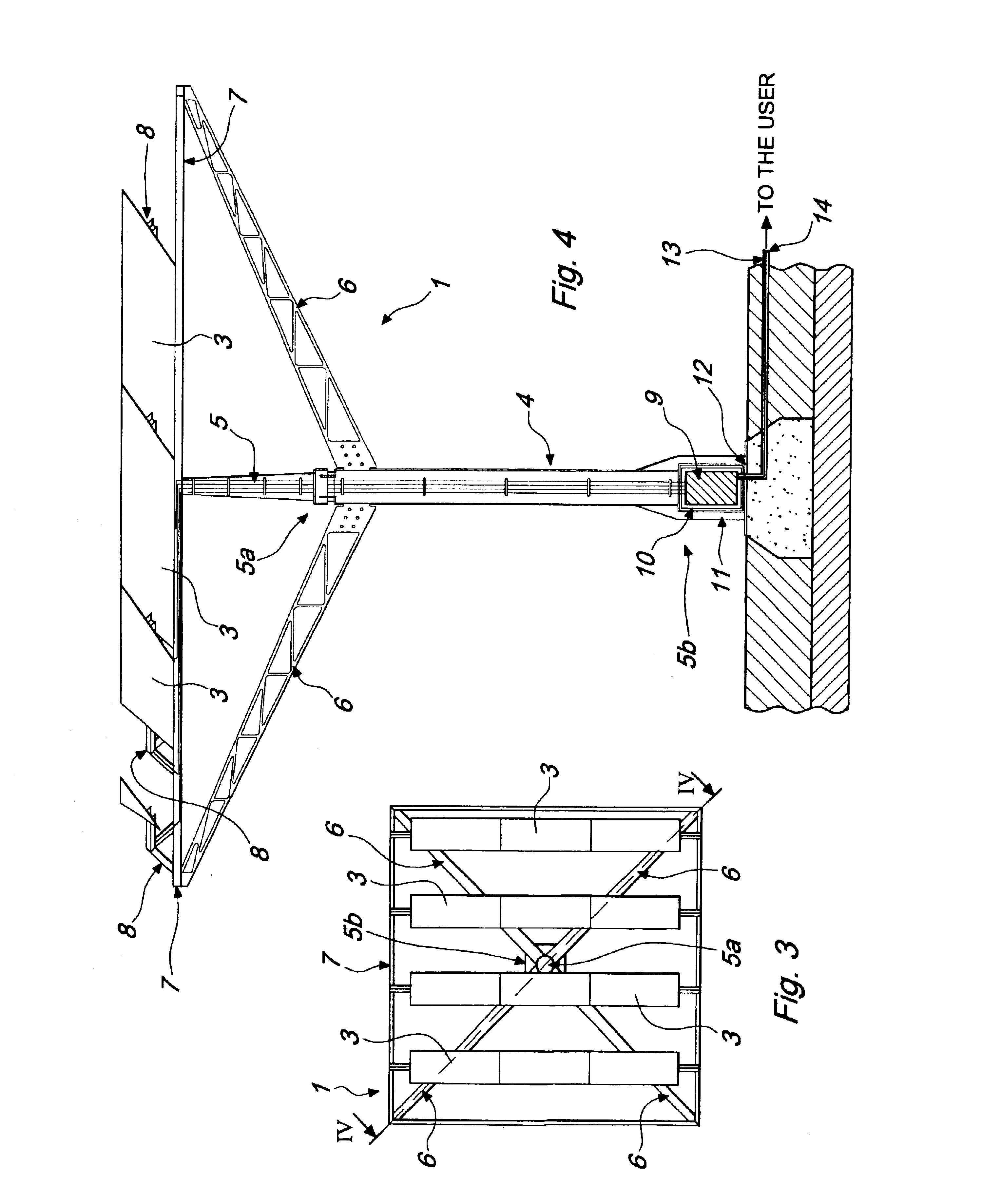
[0034]With reference to the figures, the reference numeral 1 designates a device for converting solar radiation into electric power, comprising a plurality of photovoltaic cells, schematically designated by the reference numeral 2 in FIG. 6, which are clustered into a plurality of photovoltaic modules or panels, designated by the reference numeral 3.

[0035]The device 1 is constituted by a body 4 that is substantially vertically elongated and from which multiple arms 6 protrude approximately in the vicinity of the upper end 5a of said body 4 or thereat.

[0036]In the particular embodiment described here merely by way of example, said arms 6, which are four, protrude radially and upward from said upper end 5a so as to support a frame 7 that is advantageously square or rectangular.

[0037]Said frame 7 is advantageously formed, for example, by structural elements or tubular elements that are arranged so as to form a structure that is suitable to act as a support and resting element for said ...


PUM


Abstract

A device for converting solar radiation into electric power, constituted by a substantially vertically elongated body from which multiple supporting arms for one or more modules constituted by multiple photovoltaic cells protrude in an upward region. The body is hollow and contains an inverter suitable for the conversion of electric power.

Description

BACKGROUND OF THE INVENTION[0001]The present invention relates to a device for converting solar radiation into electric power.[0002]Currently, the utilization of alternative energies, such as wind power and solar energy, has become increasingly important.[0003]In particular, over the last decades the technology related to the conversion of solar radiation into electric power has been improving; currently this conversion is commonly performed by using photovoltaic cells of a known type, such as monocrystalline or polycrystalline cells.[0004]The photovoltaic cells are arranged in succession one next to the other, so as to form a so-called photovoltaic panel or module.[0005]Known kinds of device for converting solar radiation into electric power are usually constituted by a square or rectangular photovoltaic module that is arranged on the roof of a building and is connected to a separate device for converting direct current to alternating current, commonly known as an inverter.[0006]Th...

Claims


Application Information

Patent Timeline
Patent Type & Authority Patents(United States)
IPC IPC(8): H01L31/042F24J2/54H02S20/10H02S20/30
CPCF24J2/523F24J2/54H02S20/10H02S20/30Y02B10/14Y02B10/20Y02E10/50Y10S136/291Y10S136/293Y02E10/47F24S25/10F24S30/40Y02B10/10
Inventor MATTIUZZO, GILBERTO
Owner MATTIUZZO GILBERTO
Why Eureka
Try Eureka