Pressure regulator assembly

a technology of pressure regulators and components, applied in the direction of mechanical/engine, functional valve types, transportation and packaging, etc., can solve the problems of fuel pressure regulators that are relatively expensive, subject to fuel pressure regulation shift, and non-linear in construction, so as to reduce the number of components, reduce the cost, and reduce the effect of pressure control shift robustness

Inactive Publication Date: 2005-03-24
MCGRATH DENNIS P +3
View PDF19 Cites 68 Cited by
  • Summary
  • Abstract
  • Description
  • Claims
  • Application Information

AI Technical Summary

Benefits of technology

[0007] One advantage of the present invention is that a new pressure regulator assembly is provided for a fuel system of a vehicle. Another advantage of the present invention is that the pressure regulator assembly provides a nearly constant fluid pressure over a wide range of flows. Yet another advantage of the present invention is that the pressure regulator assembly uses no elastomeric materials. Still another advantage of the present invention is that the pressure regulator assembly reduces the number of components over conventional fuel pressure regulators. A further advantage of the present invention is that the pressure regulator assembly is interchangeable with existing diaphragm type pressure regulators. Yet a further advantage of the present invention is that the pressure regulator assembly could be applied to other fluid systems such as a lubrication system. Still a further advantage of the present invention is that the pressure regulator assembly has a relatively lower cost and robustness to pressure control shift caused by aging or chemical attack of an elastomeric diaphragm. Another advantage of the present invention is that the pressure regulator assembly improves upon the poor gain control of non-elastomeric pressure regulators.
[0008] Other features and advantages of the present invention will be readily appreciated, as the same becomes better understood, after reading the subsequent description taken in conjunction with the accompanying drawings.

Problems solved by technology

Also, these fuel pressure regulators are relatively costly and are subject to fuel pressure regulation shift due to aging of the elastomeric diaphragm as well as degradation from exposure to alcohol fuels.
Also, the fuel pressure regulator has poor gain control when compared to existing elastomeric diaphragm pressure regulators.
Further, the fuel pressure regulator may use a leaf spring construction, making the regulator non-linear in construction and non-interchangeable with existing diaphragm type pressure regulators.

Method used


Image

  • Pressure regulator assembly
  • Pressure regulator assembly
  • Pressure regulator assembly

Examples


Embodiment Construction

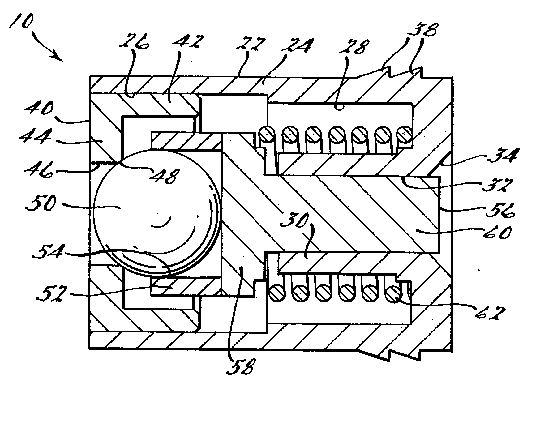
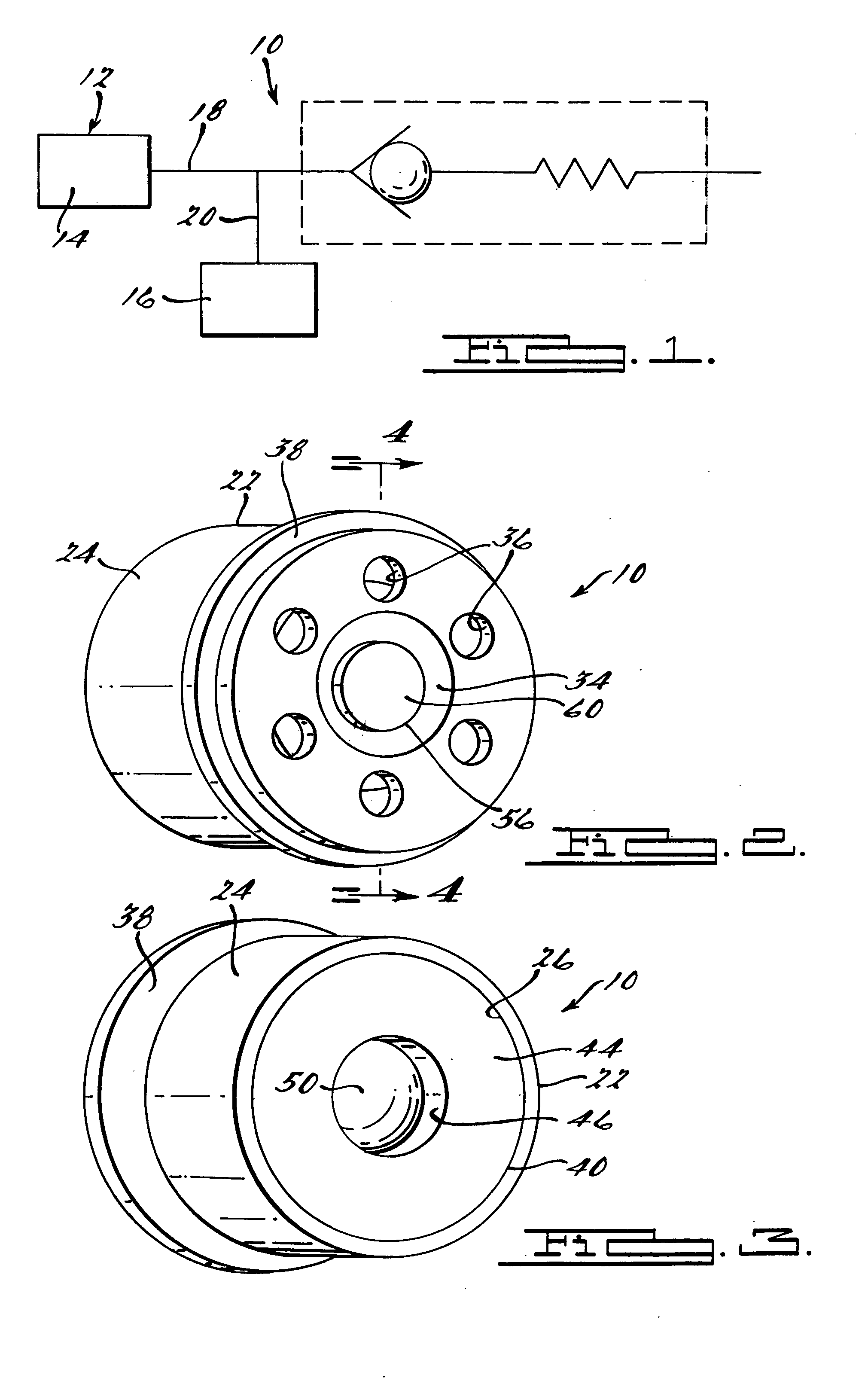
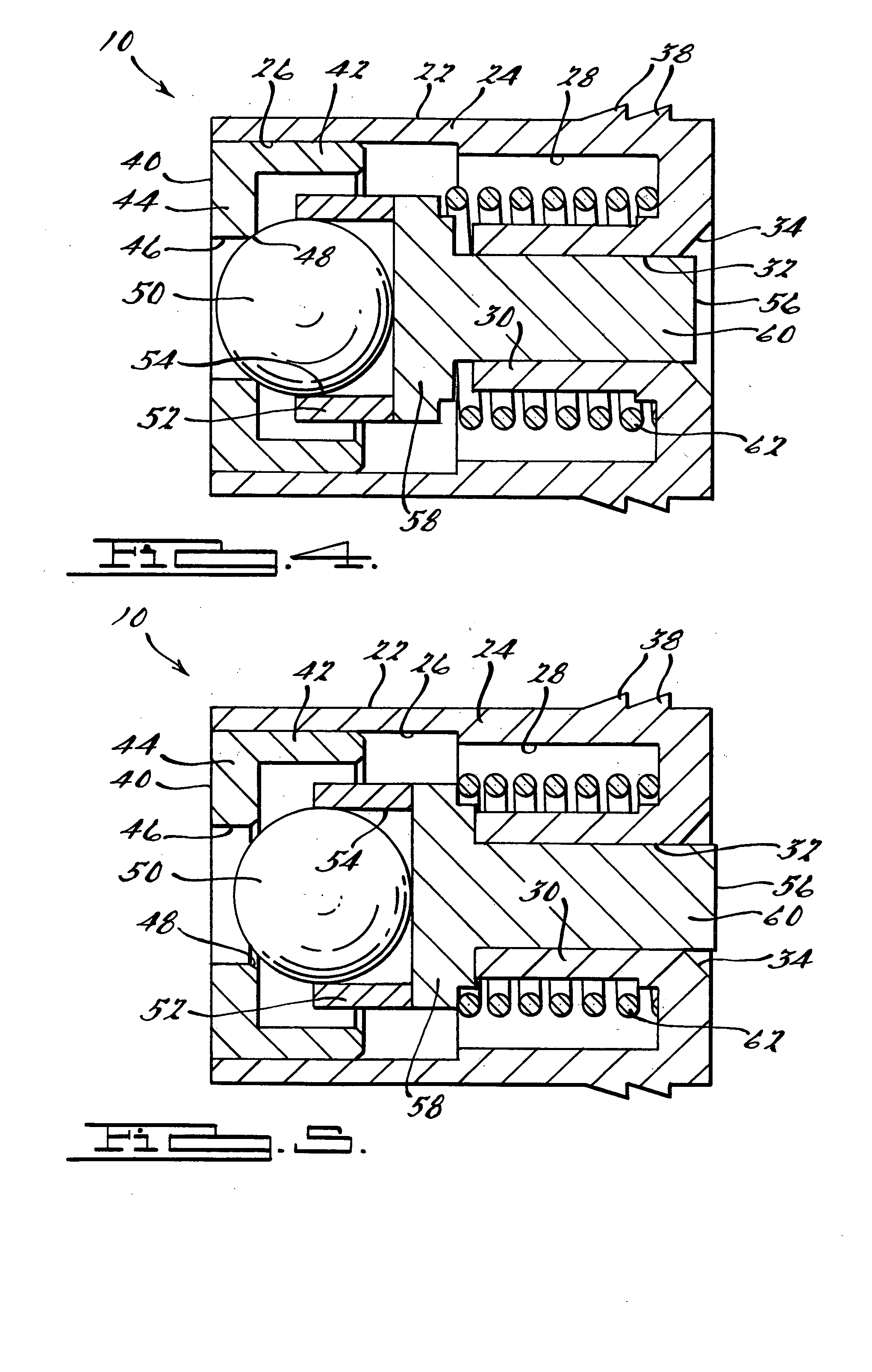
[0016] Referring to the drawings and in particular FIG. 1, one embodiment of a pressure regulator assembly 10, according to the present invention, for a fluid system, generally indicated at 12, is shown. The fluid system 12 may be a fuel system of a vehicle (not shown). The fluid system 12 includes a fluid pumping device 14 such as a fuel pump and a system 16 such as an engine. The fluid system 12 includes a first fluid inlet line 18 fluidly connecting the pressure regulator assembly 10 to the fluid pumping device 14 and a second fluid inlet line 20 fluidly connecting the first fluid inlet line 18 to the system 16. It should be appreciated that the pressure regulator assembly 10 regulates the pressure of the fluid from the fluid pumping device 14 to the system 16. It should also be appreciated that the fluid system 12 may be of a hydraulic type requiring a nearly constant fluid pressure maintained over a wide range of flows such as a lubrication system. It should further be apprecia...


PUM


Abstract

A pressure regulator assembly for a fluid system includes a housing having at least one cavity therein and a valve seat disposed in the at least one cavity and having an aperture extending therethrough. The pressure regulator assembly also includes a movable valve member disposed in the at least one cavity of the housing. The valve member has a closed position to engage the valve seat to prevent fluid from flowing into the at least one cavity and an open position to disengage the valve seat to allow fluid to flow into the at least one cavity. The pressure regulator assembly further includes a biasing mechanism disposed in the at least one cavity to bias the valve member toward the valve seat to close the aperture. The valve seat and the valve member and the biasing mechanism are aligned linearly along an axis of the valve housing.

Description

CROSS-REFERENCE TO RELATED APPLICATION(S) [0001] The present invention claims the priority date of copending U.S. Provisional Patent Application Ser. No. 60 / 505,178, filed Sep. 23, 2003 and is a continuation-in-part of copending U.S. patent application Ser. No. 10 / 688,235, filed Oct. 17, 2003.TECHNICAL FIELD [0002] The present invention relates generally to pressure regulators and, more particularly, to a pressure regulator assembly for a fuel system of a vehicle. BACKGROUND OF THE INVENTION [0003] It is known to provide a fuel tank in a vehicle to hold fuel to be used by an engine of the vehicle. It is also known to provide a fuel pump inside the fuel tank to pump fuel to the engine and a fuel pressure regulator fluidly connected to the fuel pump to regulate the pressure of the fuel to the engine. Typically, the fuel pressure regulator includes an elastomeric diaphragm, a precision machined metal valve seat, a heavy rate spring, and a mating valve cooperating with the valve seat to...

Claims


Application Information

Patent Timeline
Patent Type & Authority Applications(United States)
IPC IPC(8): F16K15/04F16K17/04G05D16/10
CPCF02M69/465F16K17/0406F16K15/044F02M69/54Y10T137/7928
Inventor MCGRATH, DENNIS P.JESWANI, PARTABROTH, ROBERT A.ANDERSON, PHILIP MOORE
Owner MCGRATH DENNIS P
Why Eureka
Try Eureka