Stent graft with branch leg

Inactive Publication Date: 2008-01-01
CARDINAL HEALTH SWITZERLAND 515 GMBH
View PDF491 Cites 217 Cited by
  • Summary
  • Abstract
  • Description
  • Claims
  • Application Information

AI Technical Summary

Benefits of technology

[0019]A typical first prosthesis includes a support or stent structure, and a foam or gasket material supported by the stent, the stent and gasket material being configured to seal the system within an artery. A typical first prosthesis also includes one or more structures or elements for engaging the second prosthesis. In preferred embodiments of the invention, these elements or structures sealing and/or matingly engage the second prosthesis. The stent is typically a synthetic or natural matrix for supporting the gasket material. In some exemplary embodiments of the stent, the stent is a hollow, substantially cylindrical, and preferably radially expandable matrix having a lumen and two open ends. The typical gasket material is a synthetic or natural fabric, tissue, foam, or the like. In preferred embodiments of the invention, the gasket material covers at least a portion of the lumen, even more preferably, the proximal end of the lumen.
[0020]A system according to the present invention is intended for repairing or bypassing an aneurysm, preferably an aortic aneurysm. The system may also be used to direct fluid flow from one portion of a fluid pathway to another. The typical system according to the invention may include multiple system components, e.g., more than one prosthesis, with the first prosthesis typically positioned upstream of an aneurysm. In preferred embodiments of the invention, the first prosthesis incl

Problems solved by technology

When left untreated, the aneurysm may rupture, usually causing rapid fatal hemorrhaging.
Although resection with a synthetic graft via transperitoneal or retroperitoneal procedure has been the standard treatment, it is associated with significant risk.
Disadvantages associated with conventional surgery, in addition to the high mortality rate, include an extended recovery period associated with the large surgical incision and the opening of the abdominal cavity, difficulties in suturing the graft to the aorta, the loss of the existing thrombosis to support and reinforce the

Method used


Image

  • Stent graft with branch leg
  • Stent graft with branch leg
  • Stent graft with branch leg

Examples


Embodiment Construction

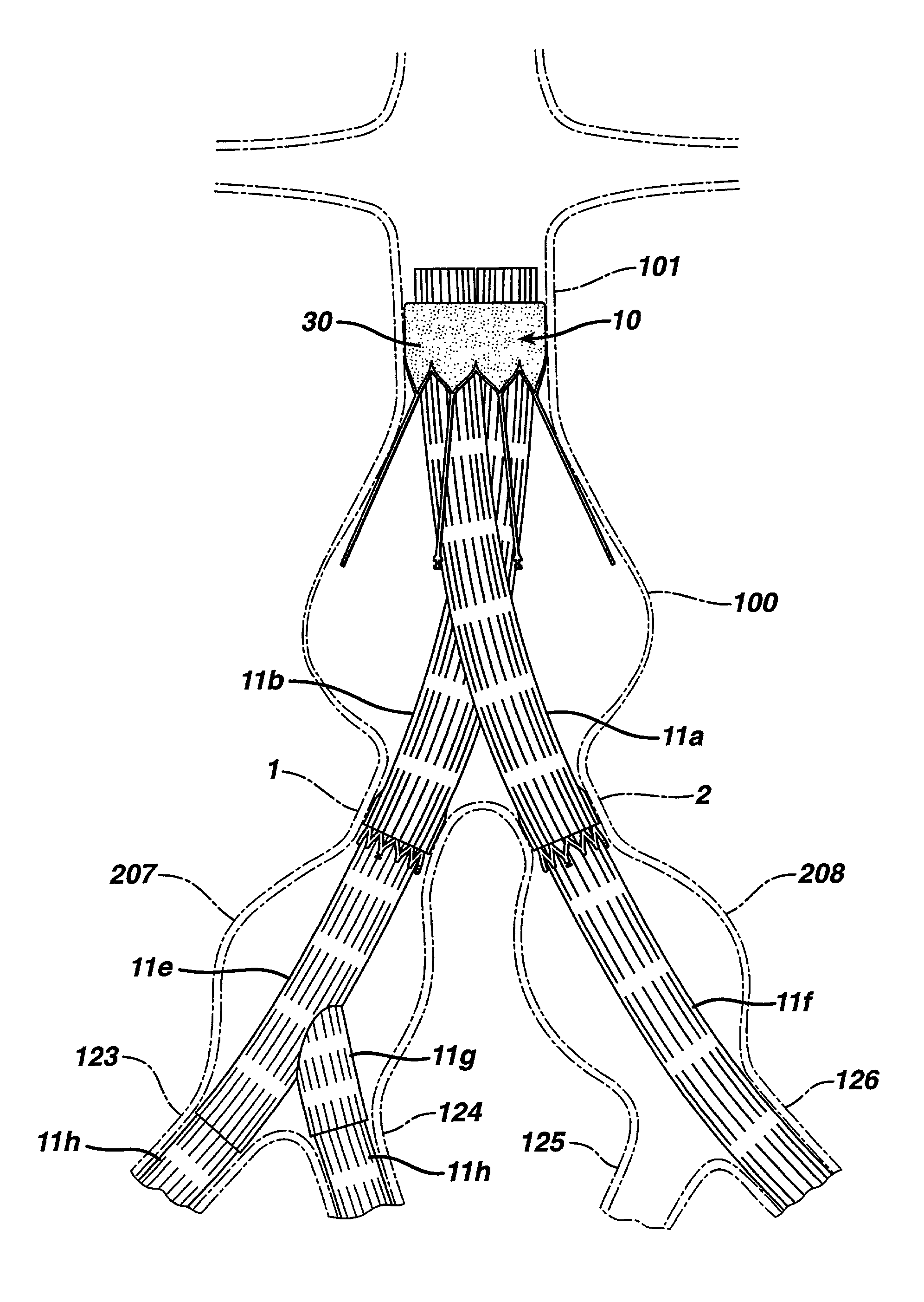
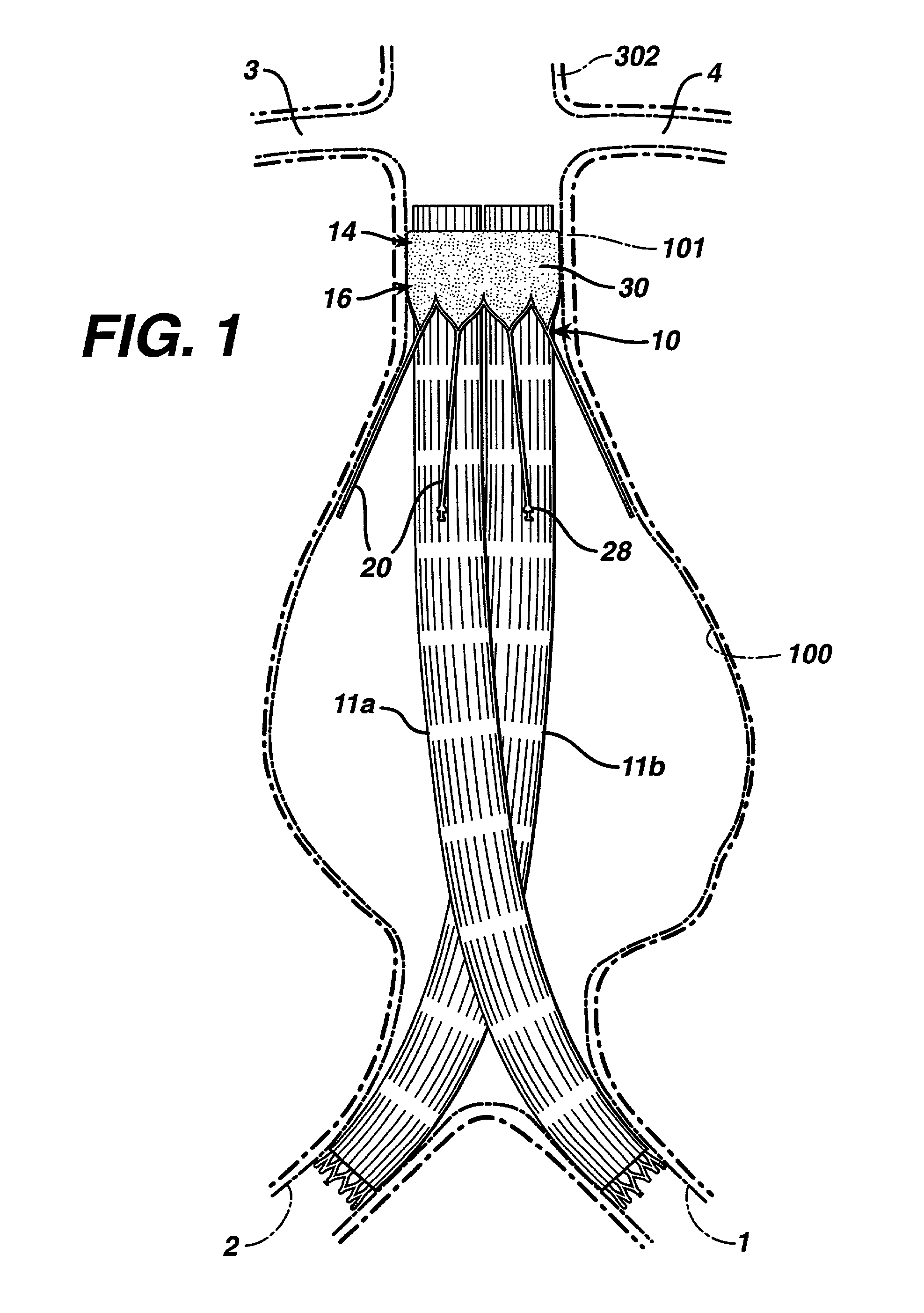
[0039]The apparatuses, systems, methods, and kits of the present invention may be used in the treatment of aortic aneurysms, preferably an abdominal aortic aneurysm, among other uses noted below. More preferably, the present invention may be used to treat Schumacher Type IIC abdominal aortic aneurysms and Type III abdominal aortic aneurysms. A better understanding of the present device and its use in treating aortic aneurysms will be achieved by reading the following description in conjunction with the above-incorporated references.

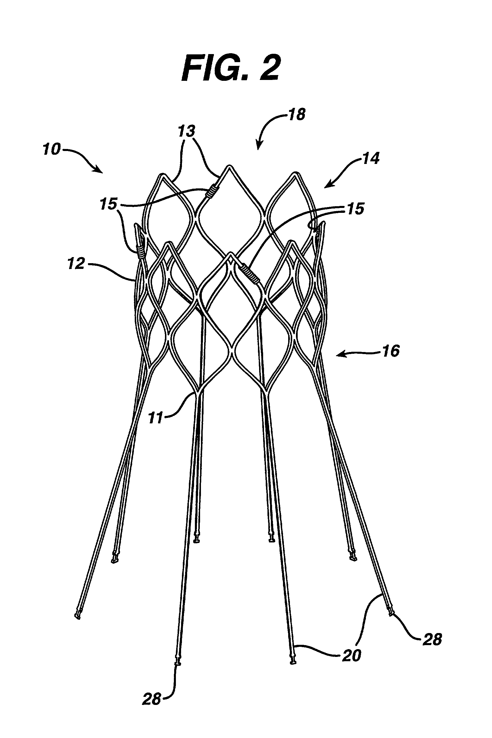
[0040]The present invention embodies a prosthesis for repairing or bypassing an aneurysm, the prosthesis comprising a graft material engaging a stent, the stent comprising a first matrix of interconnected struts configured to engage an upstream section of an artery, and a second matrix of interconnected struts configured to engage a downstream section of the artery, the stent including an intermediate portion comprising a plurality of struts extending awa...


PUM


Abstract

The present invention is directed to a system, apparatus, and method for treating, repairing, and/or replacing an aneurysm, preferably an aortic aneurysm, and most preferably, an abdominal aortic aneurysm. The systems, devices, and methods of the present invention include a first prosthesis or stent gasket, and at least one second prosthesis for bypassing the aneurysm. In preferred embodiments, the second prosthesis includes a branch leg that may be disposed and anchored in an either a cross artery or a downstream artery to facilitate fluid flow. In other preferred embodiments, at least one third prosthesis is provided for establishing a fluid flow channel through a second diseased artery to bypass an aneurysm disposed therein. In accordance with the invention, the first artery may be the abdominal aorta and the second artery may be an iliac artery.

Description

CROSS-REFERENCE TO RELATED APPLICATIONS[0001]This application is a continuation-in-part of U.S. application Ser. No. 09 / 714,080, filed on Nov. 16, 2000, now U.S. Pat. No. 6,656,215; U.S. application Ser. No. 09 / 714,093, filed on Nov. 16, 2000 now abandoned; U.S. application Ser. No. 09 / 714,078 filed on Nov. 16, 2000 now U.S. Pat. No. 6,626,938; and U.S. application Ser. No. 09 / 714,079, filed on Nov. 16, 2000 now U.S. Pat. No. 6,482,227.BACKGROUND OF THE INVENTION[0002]1. Field of the Invention[0003]The present invention relates to devices and methods for repairing aneurysms, and more particularly, to percutaneously and / or intraluminally delivered devices and methods for repairing aneurysms, such as abdominal aortic aneurysms and thoracic aortic aneurysms.[0004]2. Discussion of the Related Art[0005]An aneurysm is an abnormal dilation of a layer or layers of an arterial wall, usually caused by a systemic collagen synthetic or structural defect. An abdominal aortic aneurysm is an aneur...

Claims


Application Information

Patent Timeline
IPC IPC(8): A61F2/06A61B17/064A61B17/068A61F2/07A61F2/82A61F2/848A61F2/88A61F2/89A61F2/91A61F2/915A61F2/95
CPCA61F2/064A61F2/07A61F2/91A61F2/915A61B17/064A61F2230/0054A61F2/848A61F2/95A61F2002/061A61F2002/065A61F2002/067A61F2002/075A61F2002/825A61F2002/91525A61F2002/91541A61F2002/91558A61F2250/006A61F2/89A61F2230/0013A61F2230/005A61F2230/0067A61F2230/0078A61F2220/005A61F2220/0058A61F2220/0066A61F2220/0075A61F2230/001A61B17/0682
Inventor LANDAU, GEORGE D.RAMER, MARCSOLOVAY, KENNETH S.
Owner CARDINAL HEALTH SWITZERLAND 515 GMBH
Why Eureka
Try Eureka