Electric drill apparatus

a drill and electric technology, applied in the direction of drilling/boring measurement devices, drilling machines, manufacturing tools, etc., can solve the problems of limited drilling capability, limited use area, limited portability, etc., to improve the adhesion to workpieces, reduce size and weight, and reduce the profile

Inactive Publication Date: 2006-10-17
NITTO KOHKI CO LTD
View PDF17 Cites 764 Cited by
  • Summary
  • Abstract
  • Description
  • Claims
  • Application Information

AI Technical Summary

Benefits of technology

[0009]It is an object of the present invention to provide a low profile type electric drill apparatus having a reduced size and weight.
[0010]It is another object of the present invention to provide a low profile type electric drill apparatus which is capable of improving adhesivity to a workpiece, in a case of a small size and lightweight apparatus.
[0011]It is a further object of the present invention to provide an electric drill apparatus which is capable of automatically driving a motor again, which has been automatically stopped due to motor overload, and which has a simple configuration to improve workability.
[0012]It is a yet further object of the present invention to provide an electric drill apparatus which is capable of recognizing both a normal and overload work condition of a motor.

Problems solved by technology

Such vertically-arranged electric drill apparatuses are generally large in size, and can thus be only used in limited operation areas and have limited portability.
However, such a low profile type electric drill apparatus as above, which is small in size and light in weight suffers from a drawback in that it has a limited drilling capability since only a small adhesive force acting on an electromagnetic base is employed to secure the electric drill apparatus on a workpiece.
Further, there exists no electric drill apparatus having a function of re-driving a motor after it has been automatically stopped due to motor overload.

Method used


Image

  • Electric drill apparatus
  • Electric drill apparatus
  • Electric drill apparatus

Examples


Embodiment Construction

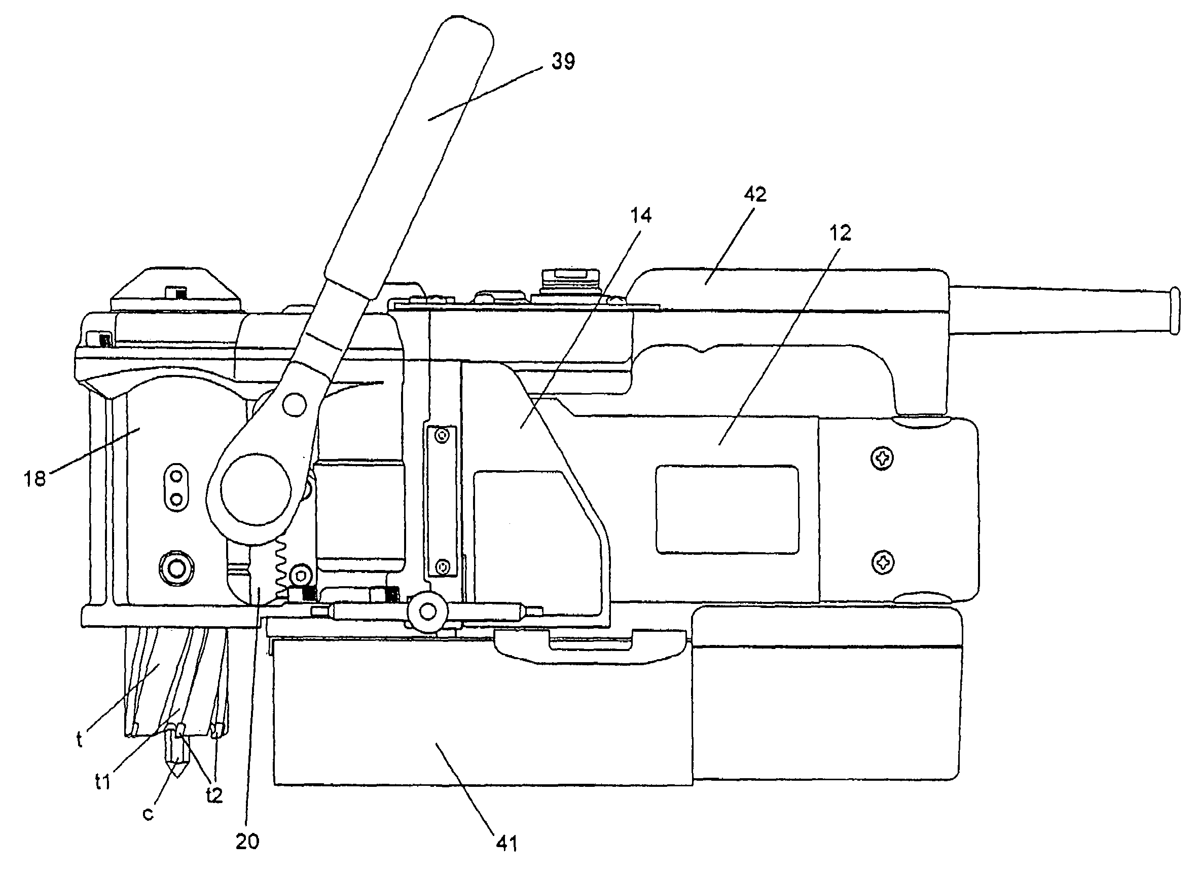
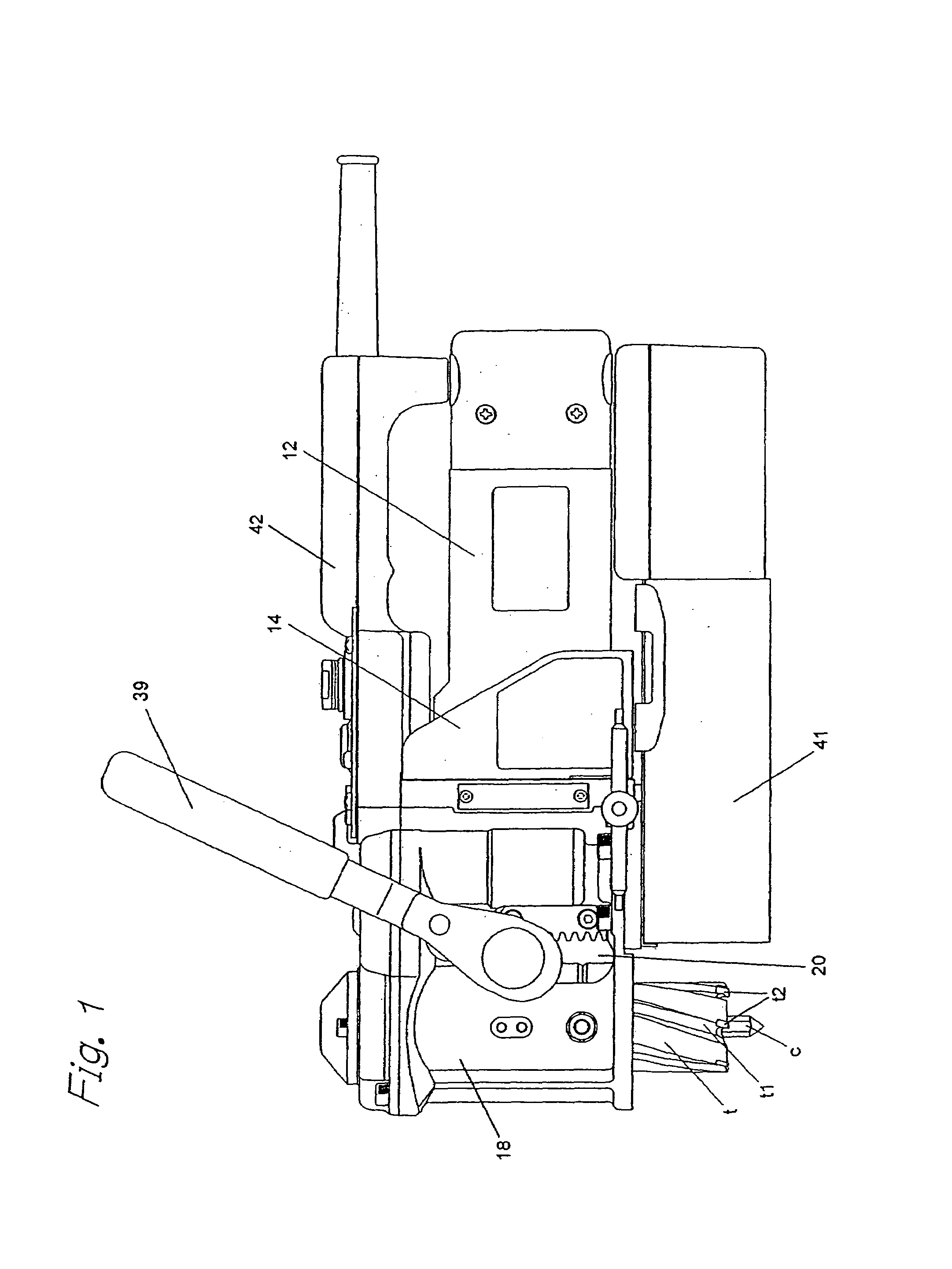
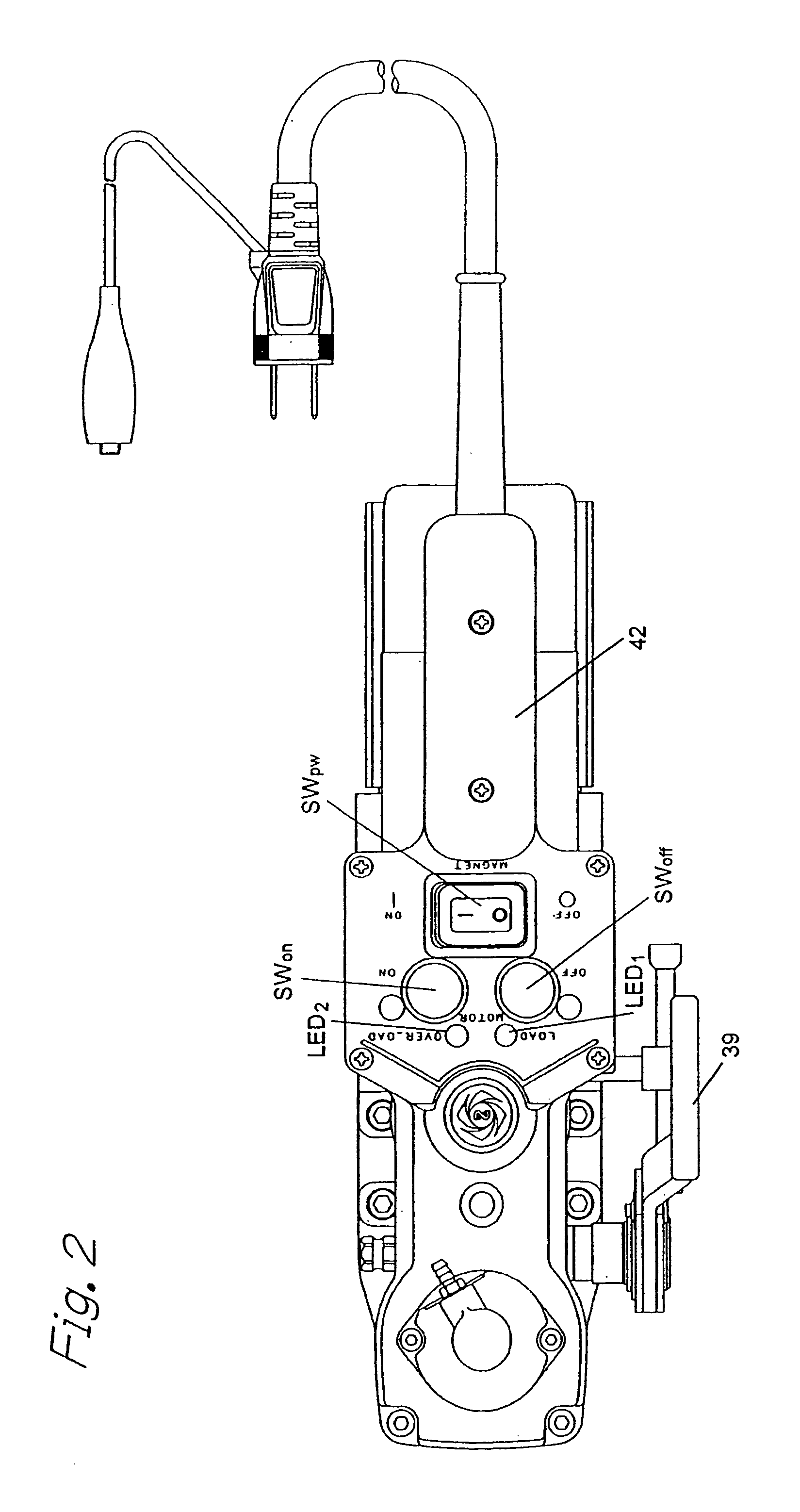
[0037]With reference to FIGS. 1–3 respectively showing front, plan and cross-sectional views, there will now be explained an electric drill apparatus having a low profile according to one embodiment of the present invention.

[0038]As shown in FIG. 1, the electric drill apparatus according to the present invention comprises a body 14 which contains a drill motor 12; a rotary shaft assembly 18 for rotating an annular cutter t attached on a lower end of the assembly 18; a feed (or slide) mechanism 20 for advancing and retracting the annular cutter t; and an electromagnetic base 41 held on a bottom of the body 14 and containing an electromagnet(s) for securing the body 14 on a steel material or the like which is to be drilled. The electric drill apparatus also comprises a manual operation lever 39 for driving the feed mechanism 20, and a handle 42 over the motor 12 at an upper position of the body 14. The motor 12 is fixed in the body 14 such that its output shaft is oriented horizontall...


PUM

PropertyMeasurementUnit
DC voltageaaaaaaaaaa
discharge time constantaaaaaaaaaa
rotational speedaaaaaaaaaa

Abstract

An electric drill apparatus having a low profile is provided which comprises an annular cutter, a motor for rotating the annular cutter, a rotary shaft assembly for rotating the annular cutter attached to its leading end about a rotating, a rotation reduction mechanism disposed between the motor and rotary shaft assembly for transmitting a driving force of the motor to the annular cutter through the rotary shaft assembly, a feed mechanism responsive to an operation of a manual handle, for moving the rotary shaft assembly along with a straight line to advance or retract the annular cutter attached to the rotary shaft assembly with respect to a workpiece, and an adhesion base for securing the electric drill apparatus to the workpiece. The annular cutter has a plurality of cutting blades comprised of cemented carbide tips fixed on its lower end, thereby it is capable of rotating at a high speed. The rotary shaft assembly has a rotating shaft which rotates in a direction different from that of a rotating shaft of the motor, thereby the drill apparatus has a low profile.

Description

BACKGROUND OF THE INVENTION[0001]The present invention relates generally to an electric drill apparatus, and more particularly to an electric drill apparatus having a low profile and adapted to automatically re-drive a drill motor when rotation of the drill motor is stopped in the event of overloading.[0002]Nowadays, in new construction, repair and the like of a variety of buildings and so on, there exists a need for drilling workpieces comprising structural materials such as a steel cage and the like at or near positions at which the workpieces are attached to buildings. It is therefore necessary to transport an electric drill apparatus to workpiece assembly places. In addition, a drilling operation must be often performed in a relatively narrow space at or near a position at which a structural material or workpiece is attached. Thus, to enable easy transportation and operation in narrow operating spaces, a reduction in size and weight is required for electric drill apparatuses.[00...

Claims


Application Information

Patent Timeline
Patent Type & Authority Patents(United States)
IPC IPC(8): B23B39/00B23B45/00B23B45/02B23B47/24B23Q11/04B25H1/00
CPCB23Q11/04B25H1/0071Y10T408/16Y10T408/6779Y10T408/13Y10T408/65Y10T408/17Y10T408/554Y10T408/165Y10T408/14B23B47/00
Inventor MIKIYA, TOSHIOSHIMADA, KEISUKEYAMAGUCHI, MUNENORICHIBA, TAKASHIOHTSUKA, KENJI
Owner NITTO KOHKI CO LTD
Why Eureka
Try Eureka