
Working machine
a technology of working machine and guard cover, which is applied in the direction of superstructure sub-units, vehicle components, construction, etc., can solve the problems of large space required for opening and closing the cover, disadvantages of the related art working machine in the points of production steps, cost and appearance of the machine, etc., and achieve the effect of simplifying the structure of the locking mechanism of the guard cover
- Summary
- Abstract
- Description
- Claims
- Application Information
AI Technical Summary
Benefits of technology
Problems solved by technology
Method used
Image

Examples
Embodiment Construction
[0023]A working machine according to the present invention will be described with reference to embodiments shown in the drawings below.
[0024]In the following embodiments, a hydraulic excavator is illustrated as an application object.
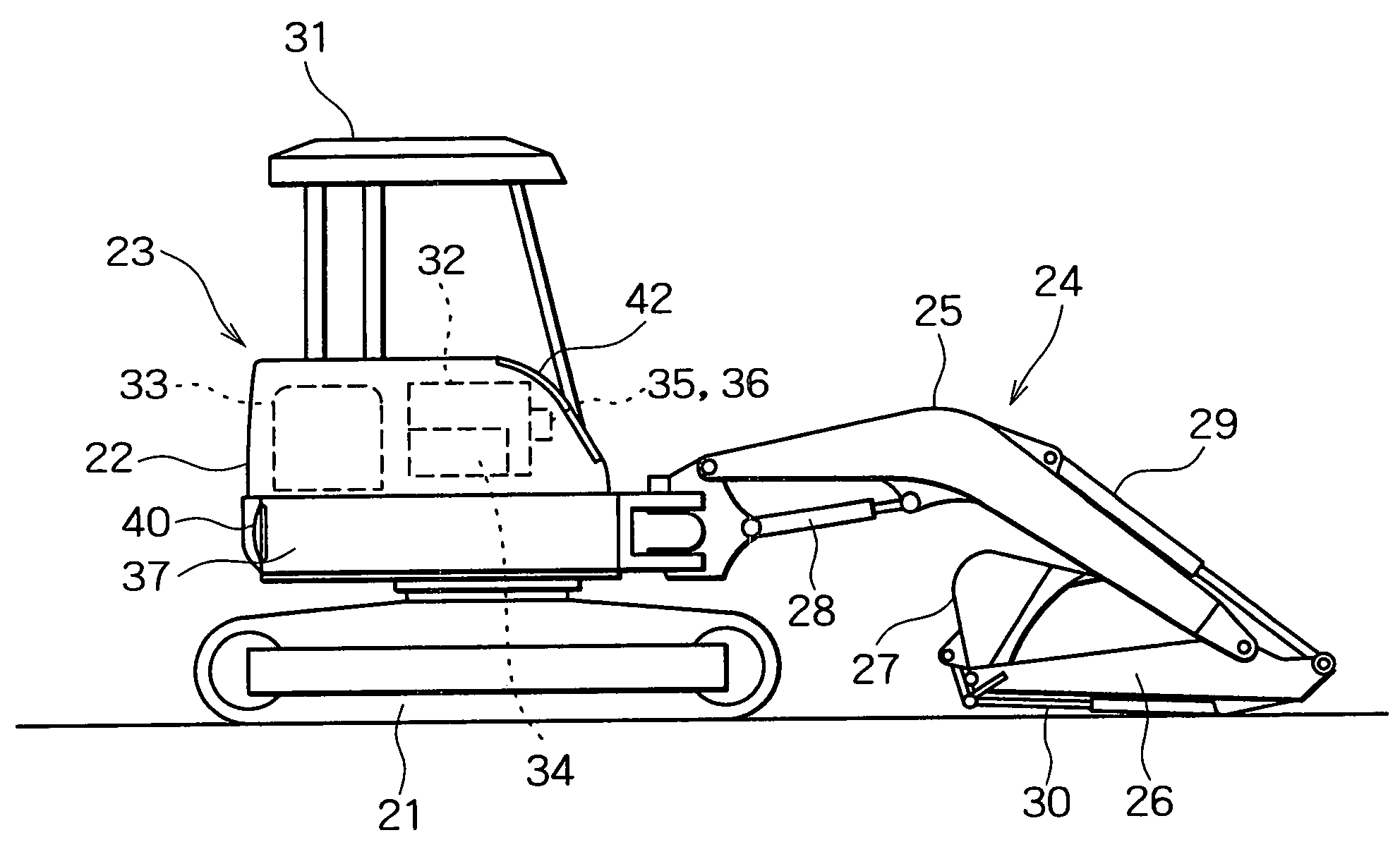
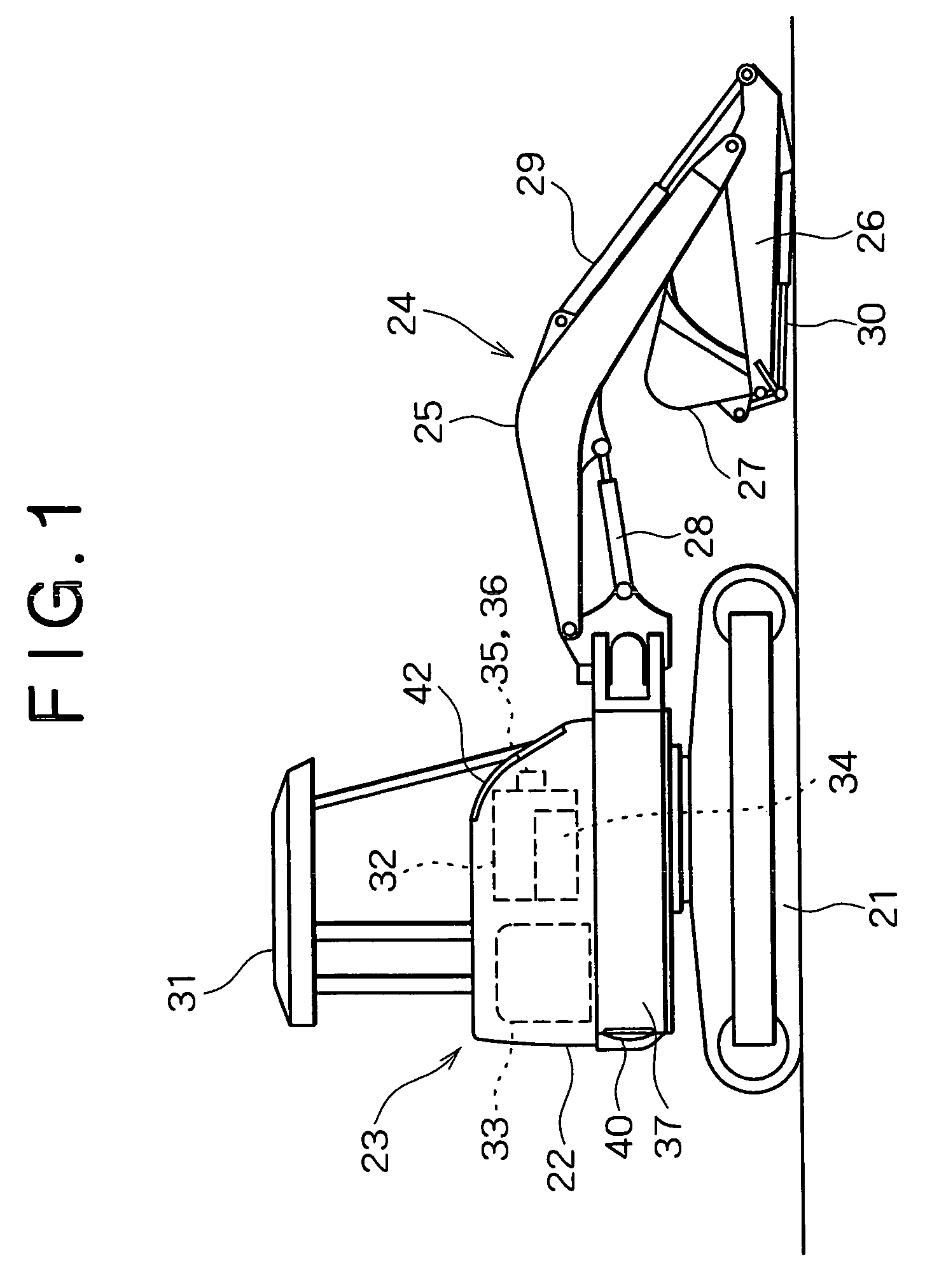
[0025]In this hydraulic excavator a base machine 23 is formed in such a manner that an upper rotating body 22 is rotatably mounted on a crawler type lower traveling body 21 around its vertical shaft, as shown in FIG. 1. Onto this base machine 23 are attached a working attachment 24 comprising a boom 25, an arm 26, a bucket 27, hydraulic cylinders 28, 29, 30 which operate them, and a swing cylinder (not shown), which swings the entire attachment in opposite directions.
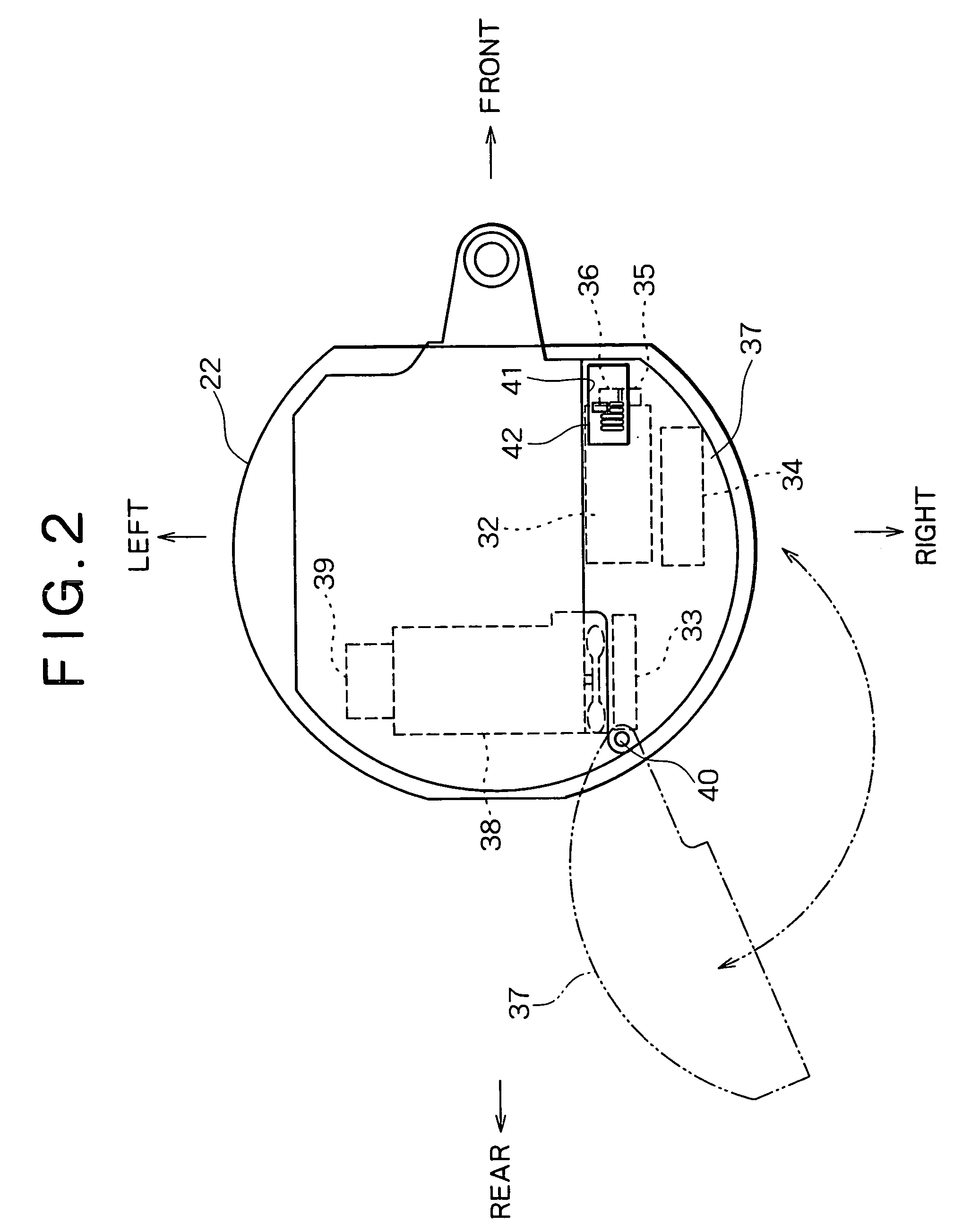
[0026]In this hydraulic excavator, as shown in FIGS. 1 and 2, the following apparatuses are disposed on an outer peripheral portion of the upper rotating body 22 (for example, a right side portion when an operator sitting on the operator's seat viewed. The example will be illustrated and exp...
PUM
 Abstract
Description
Claims
Application Information