Folding knife with puzzle piece locking mechanism

a locking mechanism and puzzle technology, applied in the field of cutting instruments, can solve the problems of three levels of complexity of the locking mechanism, and achieve the effects of simple locking mechanism, convenient use, and easy and inexpensive manufacturing

Active Publication Date: 2009-07-09
DRAGON NAILS
View PDF24 Cites 2 Cited by
  • Summary
  • Abstract
  • Description
  • Claims
  • Application Information

AI Technical Summary

Benefits of technology

[0012]The object of the present invention is to provide a folding knife locking mechanism which is basically undefeatable, that is, it cannot inadvertently close due to pressure or use and cannot suffer catastrophic failure when pressure is applied to the back edge of the knife blade when the knife blade is in an extended open position. Such a locking mechanism must be simple, account for wear and tear of use, and be self adjusting. Moreover, the locking mechanism of the present invention is specifically designed to accommodate extreme forces and withstand the application of external forces to the back of the extended blade unlike other locking mechanisms. Another object of the invention is to keep the locking mechanism simple, easy and inexpensive to manufacture, easy to use, and able to be used by many varieties of folding knife designs. It must also be able to be released or engage within the flow of use and without taking one's hands off of a safe user position.
[0014]The puzzle lock provides for an adjustment to wear. Because steel does wear, it is further the object of the invention that the angle of the cuts and the radiuses of the surfaces of the puzzle pieces allow for an infinite amount of wear and change over time which allows the puzzle piece to set itself deeper into the locking position over time. The positioning of the lock release is such that in normal use of under duress one cannot accidentally disengage the lock. Squeezing pressure of one's hands or fingers would serve to only push the male puzzle piece deeper into the female puzzle opening.
[0018]A locking mechanism is positioned proximate to the handle cavity. The locking mechanism is comprised of a male puzzle tang releasing from the liner of the scale within the handle cavity, and positioned to interlock with the matching female puzzle cavity within the heel-butt portion of the blade and the stop pin when the knife blade is in the extended position or exposed for a position of use, blade motion is stopped, allowing the male puzzle piece to slip into and interlock with the female puzzle cavity within the rear butt heel portion of the blade on the extended knife blade. In this position, when pressure is applied downward on the upper edge or back of the knife blade, the male puzzle tang is snugly interconnected and locked within the female puzzle cavity of the blade and both the puzzle pieces interlock positively to prevent inadvertent closing of the knife blade and to eliminate forward and backward motion of the extended blade.

Problems solved by technology

This type of locking mechanism has three levels of complexity as with regular puzzles pieces.

Method used


Image

  • Folding knife with puzzle piece locking mechanism
  • Folding knife with puzzle piece locking mechanism
  • Folding knife with puzzle piece locking mechanism

Examples


Embodiment Construction

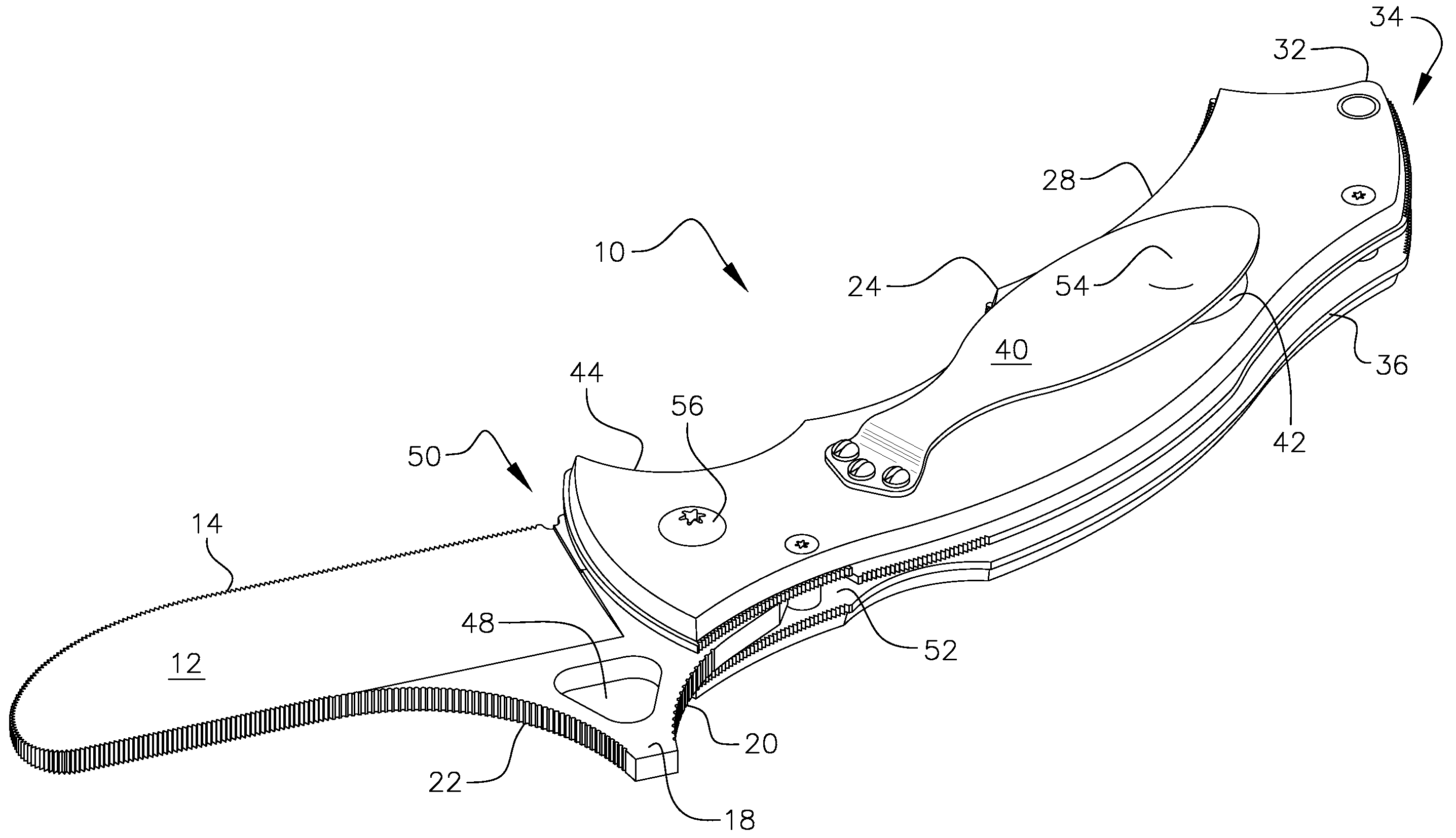
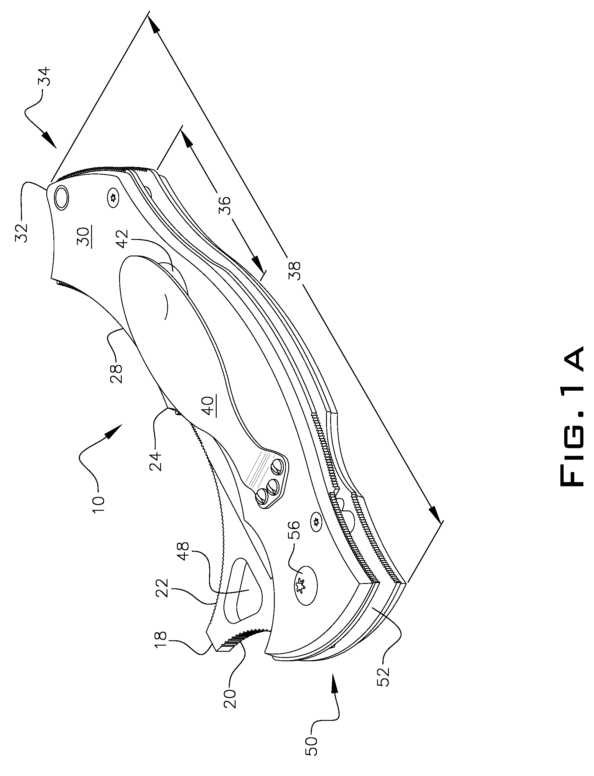
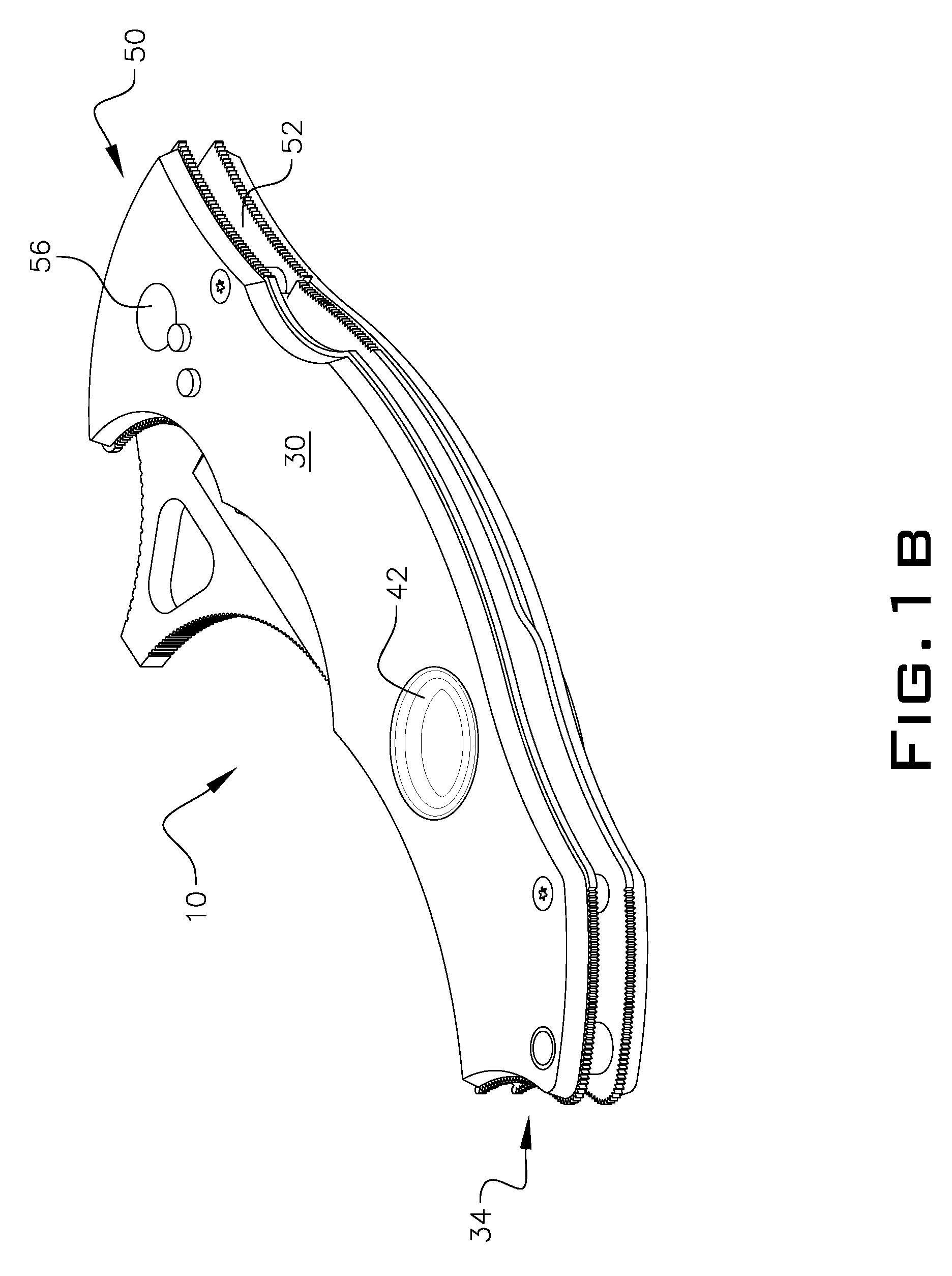
[0033]To assist the reader in understanding typical components of a knife or tool in which the inventive puzzle locking mechanism 100 may be incorporated, the following numbering and associated list of features are provided herein regarding one example of such a knife or tool. In the example of a knife or tool (generically referred to hereinafter as knife) depicted in the accompanying drawings FIGS. 1A-1C, the following features are depicted: folding knife 10, blade 12, cutting edge 14 of blade, extended thumb ramp 18, posterior curve 20 of thumb ramp, interior curve 22 of thumb ramp, handle horns 24, handle flares 28, handle assembly 30, handle finger retention point 32, handle butt end 34, handle posterior curve 36, handle length 38, clip 40, handle dimple 42, handle interior lower guard 44, finger opening aperture 48, handle forward end 50, handle cavity 52, clip spoon 54 and pivot point 56. Many of the above features are also shown in U.S. Pat. No. 6,725,545 to the inventor here...


PUM


Abstract

A locking mechanism for a folding knife or tool with a handle having a cavity defined within the handle; a knife or tool blade having a heel-butt end with a female puzzle cavity portion cut out of a rear side of the heel-butt end, and the heel-butt end being rotationally interconnected to the front end of the handle wherein the knife or tool blade travels between an extended position and a closed position within the handle cavity; and a matching male puzzle portion at an end of a tang portion configured for engaging snugly and interconnectively with the female puzzle cavity portion at the heel-butt of the blade.

Description

FIELD OF THE INVENTION[0001]The invention relates to cutting instruments and specifically to edged tools referred to as knives and more specifically to folding knives with locking mechanisms contained within them to prevent the inadvertent closing of the knife blade associated with folding knives during normal use, extreme or hard use, or the simple act of holding the folding knife, and unlike existing locking mechanisms the invention allows direct pressure against the locking motion.BACKGROUND OF THE INVENTION[0002]Cutting instruments or edged tools have been used by many types of people and industries for hundreds of years: all of them needing an edge that separates matter or simply cuts, be they crafts people, butchers, hunters, carpenters, warriors, law enforcement personnel or others. Edged tools allow for civilizations to grow and expand through the work that cutting tools enable us to do. Civilization depends on the act of cutting things. Over time these edged tools have gone...

Claims


Application Information

Patent Timeline
Patent Type & Authority Applications(United States)
IPC IPC(8): B26B1/04
CPCB26B1/044
Inventor FRANK, BRAM
Owner DRAGON NAILS
Why Eureka
Try Eureka