Apparatus for indicating fluid pressure in a conduit

a technology of fluid pressure and apparatus, which is applied in the direction of volume/mass flow by differential pressure, process and machine control, instruments, etc., can solve the problems of high cost, inability to allow patients to be ambulatory, and devices that are generally operating in a reasonably satisfactory manner, and are often quite complex

Inactive Publication Date: 2000-01-04
PESCADERO BEACH HLDG
View PDF4 Cites 76 Cited by
  • Summary
  • Abstract
  • Description
  • Claims
  • Application Information

AI Technical Summary

Problems solved by technology

The devices range from simple pressure gages to highly complex mechanical and electrical detectors and flow meters.
Pole mounted pumps such as these, provide accurate systems for delivery, but are typically expensive to use and do not allow the patient to be ambulatory as they require an external power source.
The prior art devices, while generally operating in a reasonably satisfactory manner, are often quite complex, difficult to maintain frequently require external...

Method used


Image

  • Apparatus for indicating fluid pressure in a conduit
  • Apparatus for indicating fluid pressure in a conduit
  • Apparatus for indicating fluid pressure in a conduit

Examples


Embodiment Construction

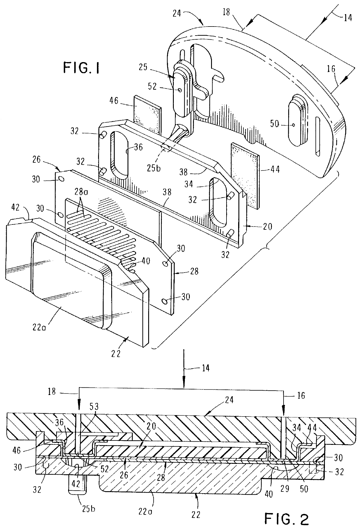
Referring to the drawings and particularly to FIGS. 1 and 2, one form of the fluid flow indicator means of the invention is there shown in fluid communication with a main fluid supply line 14 that branches into first and second feeder lines or conduits 16 and 18 respectively. The indicator means here comprises an indicator base or platform 20 which is connected to a support or lens plate 22 having a viewing lens portion 22a. Connected to a substrate 24 is an outlet port assembly 25 which has a fluid outlet port 25b.

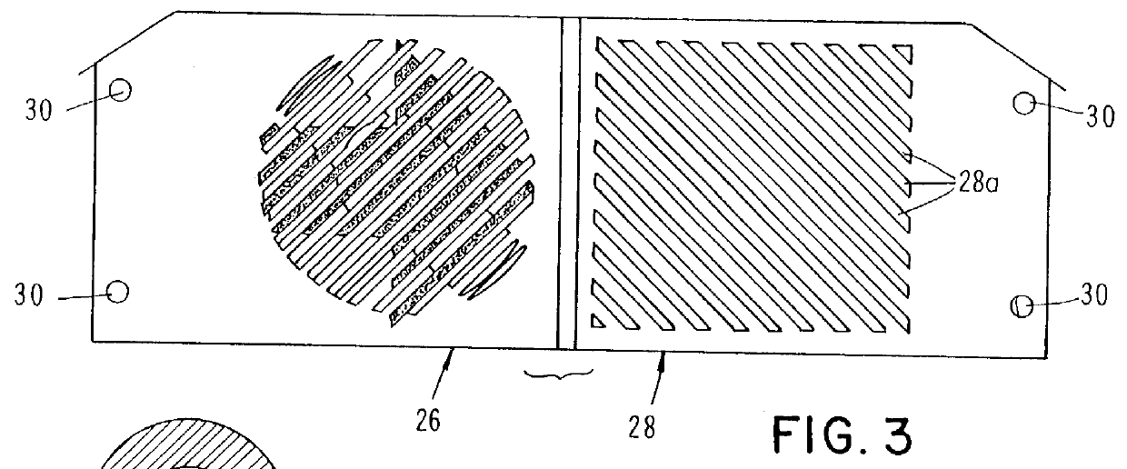
Disposed between platform 20 and plate 22 are first and second indicia-carrying means shown here as thin films 26 and 28. Films 26 and 28, which are in intimate contact, are preferably constructed from a substantially transparent, flexible material such as mylar. It is to be understood that the indicia-carrying means can take various forms and can comprise any structure having a surface that will display a selected indicia. As indicated in FIG. 3, the downstream surface o...


PUM


Abstract

An apparatus for visually indicating fluid flow through a fluid system or apparatus such as a medical infusion device. The apparatus comprises a pair of thin, indicia bearing films disposed in an overlaying relationship. These films are shifted relative to each other by movement of mechanical actuators which are deflected solely by the pressure of the fluid within the fluid conduits of the system of the apparatus. The two films are stacked in closed proximity and are preferably constructed from a substantially transparent flexible material such as mylar. One surface of the inferior film is printed with a plurality of integrated symbols depicting various fluid flow conditions. The superior film functions as a mask over the inferior film and is printed with a pattern of diagonally extending, alternating clear and opaque stripes. The print ratio of the superior film permits viewing at any one time of only one of the symbols printed on the inferior film.

Description

The present invention relates generally to devices for indicating fluid flow through fluid conduits. More particularly, the invention concerns a mechanical fluid flow indicator for providing a clear visual indication of fluid flow through one or more fluid conduits with which the indicator is associated.DISCUSSION OF THE PRIOR ARTThe prior art is replete with devices for detecting and measuring fluid flow through fluid conduits. The devices range from simple pressure gages to highly complex mechanical and electrical detectors and flow meters.Fluid flow indicating devices find application in numerous fields including chemical, industrial and medical fields. In the medical field a number of diverse applications exist for fluid delivery systems that incorporate a means for indicating the status of fluid flow to the patient. For example, traditional gravity feed intravenous delivery systems often incorporate a flow indicator that is positioned in the fluid delivery line that connects th...

Claims


Application Information

Patent Timeline
IPC IPC(8): A61M5/168A61M5/145A61M5/152G01P13/00A61M37/00G01F1/38G01L7/00G01L7/02
CPCA61M5/152A61M5/16854A61M5/16886G01P13/0026G01P13/0066G01P1/08A61M2205/583A61M2209/045
Inventor KRIESEL, MARSHALL S.ARNOLD, STEVEN M.GARRISON, JAMESKAZEMZADEH, FARHAD
Owner PESCADERO BEACH HLDG
Why Eureka
Try Eureka