Electrical connector and electrical connector assembly

Inactive Publication Date: 2012-09-06
DAIICHI SEIKO CO LTD
View PDF49 Cites 3 Cited by
  • Summary
  • Abstract
  • Description
  • Claims
  • Application Information

AI Technical Summary

Benefits of technology

[0022]According to such configuration, when an electrical connector is fitted, the contact part of the conductive contact is in a state engaged with interference preventing recess and a lock function is obtained, and by just that much, the lock mechanism of the electrical connector is simplified, and the local concentration of the fitting force is relieved, and thus the endurance especially in repeated attaching/detaching is improved.
[0023]As stated above, the present invention is configured in such a manner that, by a configuration in which the connected leg provided on the connector main body to which the terminal portion of the signal transmitting medium is connected is moved in either one of the extending directions of the fit fixing part provided on the product case, and the product case is sandwiched by the connected leg and the conductive contact in the thickness direction, a stand-alone connector is directly fitted to the wall of the product case, and in the fitting state of a stand-alone connector, by bringing a contact part of conductive contact into contact with a conductive path such as a signal transmitting wiring pattern formed on the surface of a product case, the electrical connection of a signal transmitting medium can be performed in a simple configuration requiring no involvement of a conventionally used circuit board and other electrical connector which is to be a fitting mate implemented on the circuit board, and the reduction in parts count and omitting soldering im

Problems solved by technology

In order to omit the receptacle connector 3, directly soldering a connected leg part of plug connector 5 to a conductive path on the product case 1 may be considered; however, heat resistance is low and direct soldering to the product case and implementation of an ele

Method used


Image

  • Electrical connector and electrical connector assembly
  • Electrical connector and electrical connector assembly
  • Electrical connector and electrical connector assembly

Examples


first embodiment

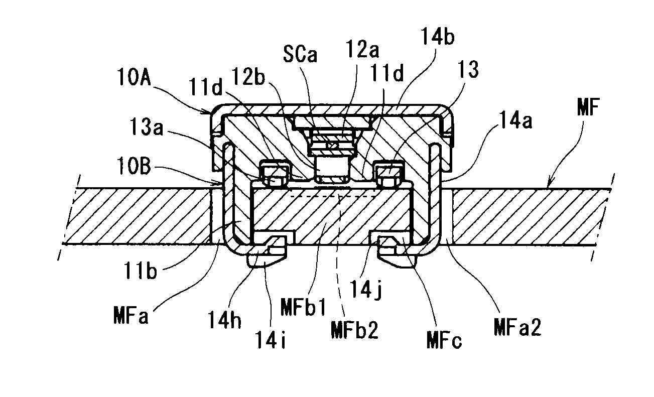
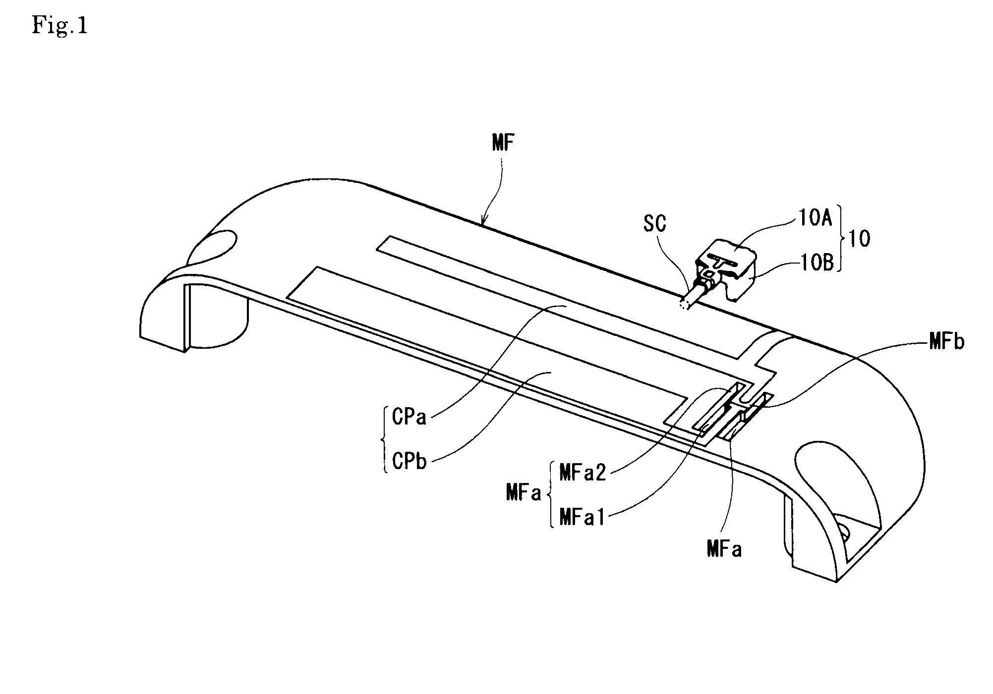
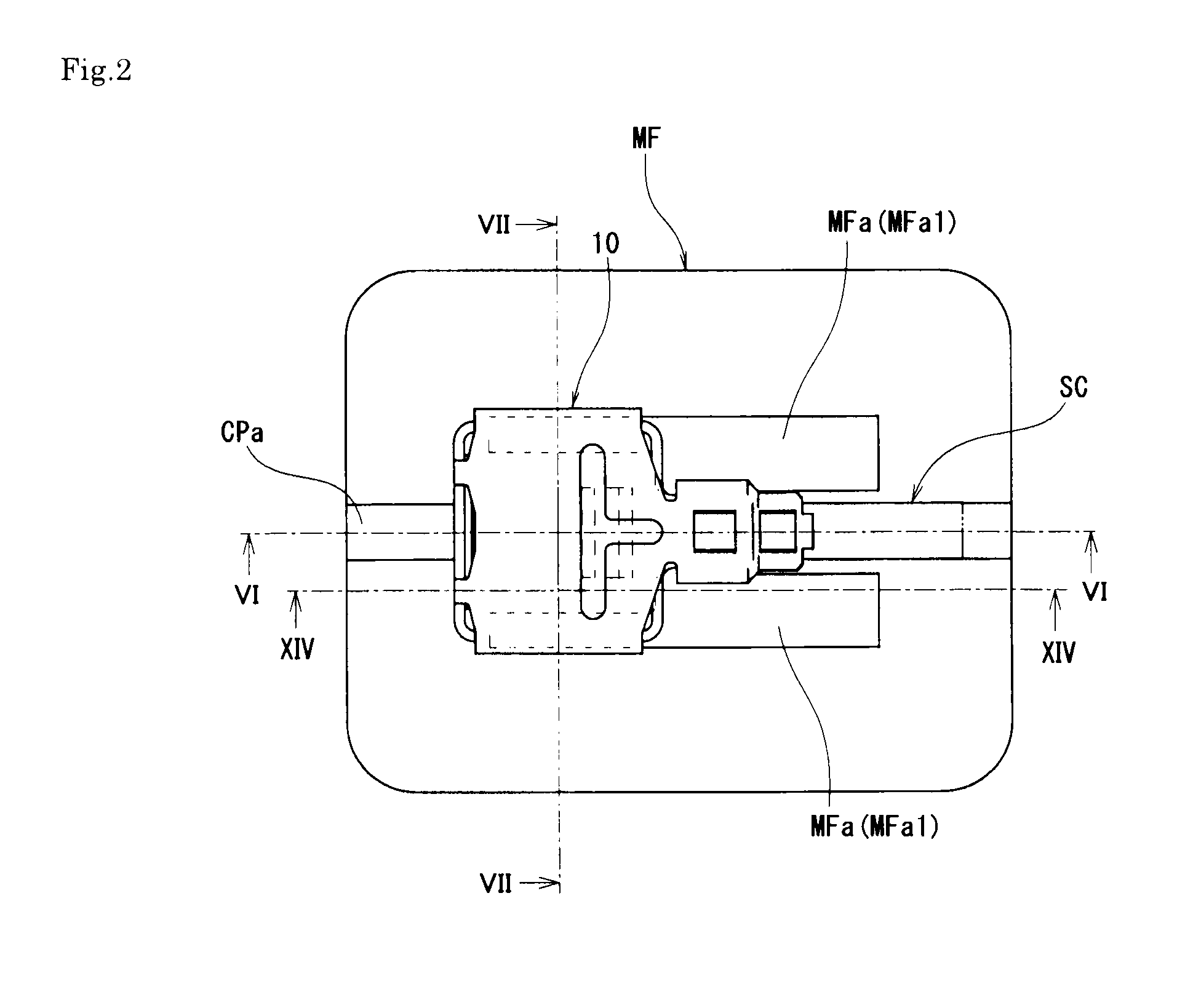
[0045]That is, a plug connector 10 according to the present invention shown in FIG. 1 to FIG. 15 is provided with a configuration for electrically connecting a terminal portion of a thin coaxial cable SC as a signal transmitting medium to a wiring pattern conductive path CP formed on the outer surface of a wall of a product case MF that constitutes an electronic device such as a mobile telephone having a predetermined electronic circuit, and a wiring pattern conductive path CP that constitutes a part of an antenna or various types of circuits is formed on the outer surface of the wall making up the product case MF by printing or the like. In addition, the shape of the product case MF is partially extracted and shown in FIG. 2 to FIG. 19.

[0046]A pair of fit connecting holes MFa, MFa are formed in parallel with each other on the wall of the product case MF so as to penetrate through the wall of product case MF, and a fit fixing part MFb formed in a beam shape is defined in a portion b...

fourth embodiment

[0100] having such configuration, when the plug connector 10 is fitted, the contact part 13a of the grounding conductive terminal (ground contact) 13 is in a state engaged with the interference preventing recess MFd′ and a lock function is obtained, by just that much, the configuration of the lock mechanism of the plug connector 10 is simplified, and the local concentration of the fitting force is relieved, and thus the endurance especially in repeated attaching / detaching is improved.

[0101]While the invention made by the present inventor has been specifically described above, the present embodiment is not limited to the abovementioned embodiment, and it goes without saying that various variations can be made without departing from the scope thereof.

[0102]For example, in the abovementioned embodiment, the engagement locking part 14j in the plug connector 10 side is formed in a convex shape, and the lock locking part MFc in the product case MF side is formed in a concave shape; howeve...


PUM


Abstract

A configuration in which a stand-alone plug connector is directly fitted to the wall of a product case, and in the fitting state of the stand-alone plug connector, the contact part of a contact comes in contact with the contact part of a wiring pattern conductive path exposed on the surface of a fit connecting hole, and the electrical connection of a signal transmitting medium can be performed in a simple configuration.

Description

BACKGROUND OF THE INVENTION[0001]1. Field of the Invention[0002]The present invention relates to an electrical connector and an electrical connector assembly which are for electrically connecting a terminal portion of a signal transmitting medium to a conductive path formed on a surface of a product case.[0003]2. Description of the Related Art[0004]In general, in various types of electronic devices or electric devices such as a mobile telephone, connecting a terminal portion of various types of signal transmitting media comprising a thin coaxial cable, a flexible wiring substrate, a printed wiring substrate or the like to a printed wiring substrate side with the use of an electrical connector has been widely practiced (for example, see Japanese Unexamined Patent Application Publication No. 2001-43939). The electrical connector is for connecting a terminal portion of a signal transmitting medium to a predetermined wiring pattern (circuit); however, normally, for example shown in FIG....

Claims


Application Information

Patent Timeline
IPC IPC(8): H01R4/48
CPCH01R12/7023H01R12/714H05K1/0284H05K2201/0999H01R12/721
Inventor TAGAWA, TETSUYAHIRAKAWA, TAKESHI
Owner DAIICHI SEIKO CO LTD
Why Eureka
Try Eureka