Method of controlling the exhaust gas temperature for after-treatment systems on a diesel engine using a variable geometry turbine

a turbine and variable geometry technology, applied in the direction of liquid fuel engines, machines/engines, mechanical equipment, etc., can solve the problems of engine non-compliance with government regulations, exhaust gas temperature falling below the desired threshold temperature, after-treatment system accumulation of undesirable accumulations, etc., to reduce the size of the fluid flow area and reduce the size of the exhaust gas heating

Inactive Publication Date: 2006-12-19
CUMMINS INC
View PDF35 Cites 24 Cited by
  • Summary
  • Abstract
  • Description
  • Claims
  • Application Information

AI Technical Summary

Benefits of technology

[0008]Yet another form of the present invention contemplates a method comprising: operating a turbocharger including a swing vane variable geometry turbine having a plurality of guide vanes, the turbine including an inlet passage having an exhaust gas flow area adapted for the flow of exhaust gas, the exhaust gas flow area having a first area for an internal combustion engine operating in a normal operating range; determining a first temperature of the exhaust gas proximate the outlet of the variable geometry turbocharger; swinging the plurality of guide vanes within the variable geometry turbine to reduce the size of the exhaust gas flow area from the first area to a reduced area if the first temperature does not satisfy a threshold temperature; and, flowing a portion of the exhaust gas entering the inlet passage around the plurality of guide vanes of the variable geometry turbine.

Problems solved by technology

The threshold temperature is generally recognized as being within a range of about 500° F. to about 700° F. The operation of the after-treatment system below the threshold temperature range will cause the after-treatment system to build up undesirable accumulations.
Further, prolonged operation of the after-treatment system below the threshold temperature without regeneration will disable the after-treatment system and cause the engine to become non-compliant with government regulations.
However, light load conditions and / or cold ambient temperatures often cause the exhaust gas temperature to fall below the desired threshold temperatures.

Method used


Image

  • Method of controlling the exhaust gas temperature for after-treatment systems on a diesel engine using a variable geometry turbine
  • Method of controlling the exhaust gas temperature for after-treatment systems on a diesel engine using a variable geometry turbine
  • Method of controlling the exhaust gas temperature for after-treatment systems on a diesel engine using a variable geometry turbine

Examples


Embodiment Construction

[0023]For the purposes of promoting understanding of the principles of the invention, reference will be made to the embodiments illustrated in the drawings and specific language will be used to describe the same. It will nevertheless be understood that no limitation of the scope of the invention is hereby intended and alterations and modifications in the illustrated device, and further applications of the principles of the present invention as illustrated herein being contemplated as would normally occur to one skilled in the art to which the invention relates.

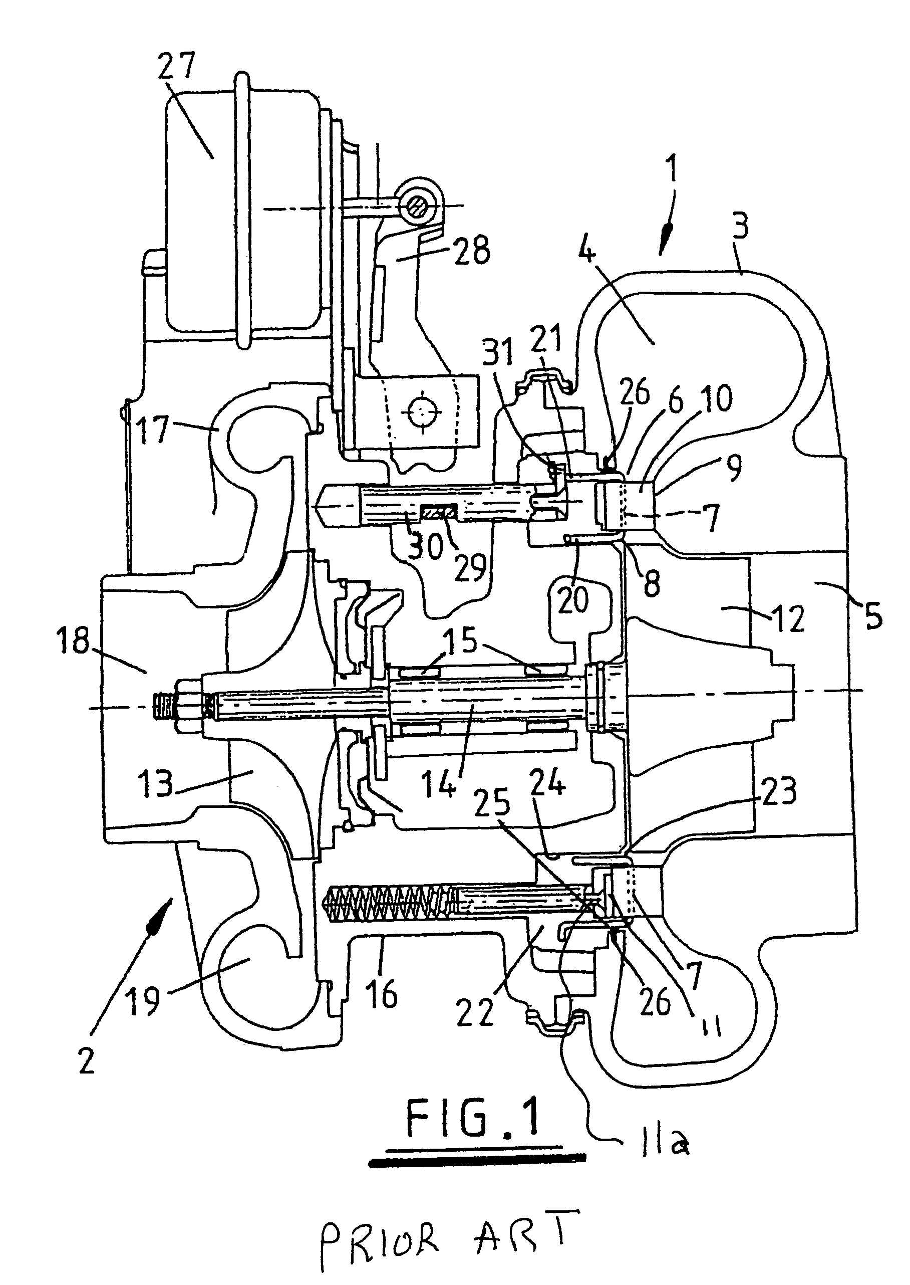
[0024]Turbochargers are well known devices for supplying air to the intake of an internal combustion engine at pressures above atmospheric (boost pressures). A conventional turbocharger essentially comprises an exhaust gas driven turbine wheel mounted on a rotatable shaft within a turbine housing. Rotation of the turbine wheel rotates a compressor wheel mounted on the other end of the shaft within a compressor housing. The com...


PUM


Abstract

A method for controlling a variable geometry turbine of a turbocharger to increase the temperature of the exhaust gas delivered to an after-treatment system. In one form the method includes reducing a fluid flow area to the turbine below a normal size and bypassing a portion of the exhaust gas around a plurality of guide vanes.

Description

CROSS-REFERENCE TO RELATED APPLICATIONS[0001]The present application is a continuation of U.S. patent application Ser. No. 10 / 840,057 filed May 6, 2004, which is a continuation-in-part of U.S. patent application No. 10 / 717,232 filed Nov. 19, 2003 now U.S. Pat. No. 6,931,849, which is a continuation-in-part of U.S. patent application Ser. No. 10 / 659,857 filed Sep. 11, 2003 now abandoned, which claims priority to British Patent Application No. 0226943.9 filed Nov. 19, 2002. Each of the above applications is incorporated herein by reference.BACKGROUND OF THE INVENTION[0002]The present invention relates generally to a method of controlling a variable geometry turbine. More particularly, but not exclusively, the present invention relates to a method for controlling a variable geometry turbocharger to affect a diesel engines exhaust gas temperature to a desired level for after-treatment systems.[0003]After-treatment system performance is directly related to the temperature of the exhaust ...

Claims


Application Information

Patent Timeline
Patent Type & Authority Patents(United States)
IPC IPC(8): F02D23/00F01D17/12F01N3/00F01D17/14F01D17/16F01N5/00F02B37/24F02B37/12F02C6/12
CPCF01D17/143F01D17/165F01D17/167F02C9/18F02D23/00Y02T10/144F05D2220/40Y02T10/12F01D17/105F01D17/14F02C6/12F02B37/22
Inventor MULLOY, JOHN M.PRINGLE, SAM
Owner CUMMINS INC
Why Eureka
Try Eureka