Matrix-type display device

a display device and matrix-type technology, applied in the field of matrix-type display devices, can solve the problems of increased cost of parts and manufacturing, increased construction complexity, and increased cost of the larger screen and higher definition, so as to suppress the deterioration of image quality due to blurred moving image, and suppress the effect of larger and more complicated construction

Inactive Publication Date: 2007-01-09
PANASONIC LIQUID CRYSTAL DISPLAY CO LTD +1
View PDF22 Cites 46 Cited by
  • Summary
  • Abstract
  • Description
  • Claims
  • Application Information

AI Technical Summary

Benefits of technology

[0006]Accordingly, it is an object of the present invention to provide a display device, which can suppress the larger and more complicated construction and which can suppress the deterioration in image quality due to blurred moving images.
[0008]According to the present invention, there is an advantage that the deterioration in image quality due to blurred moving image can be suppressed by inserting blanking data to image data. Furthermore, according to the present invention, the increase in the number of drain drivers can be suppressed by selecting a line in which image data and blanking data are displayed in one frame period, which produces an advantage that the larger and more complicated construction can be suppressed.

Problems solved by technology

Therefore, the costs for parts and manufacturing are increased.
Furthermore, the construction becomes larger and more complicated.
As a result, the costs on the larger screen and higher definition are more increased than those for the general panel.
Thus, the liquid crystal display panel is limited as a high-end type for the multimedia applications.
Thus, the efficiency of the mass production is reduced when a variety of the products are produced in large quantities.

Method used


Image

  • Matrix-type display device
  • Matrix-type display device
  • Matrix-type display device

Examples


first embodiment

[0098]A first embodiment of the present invention will be described below.

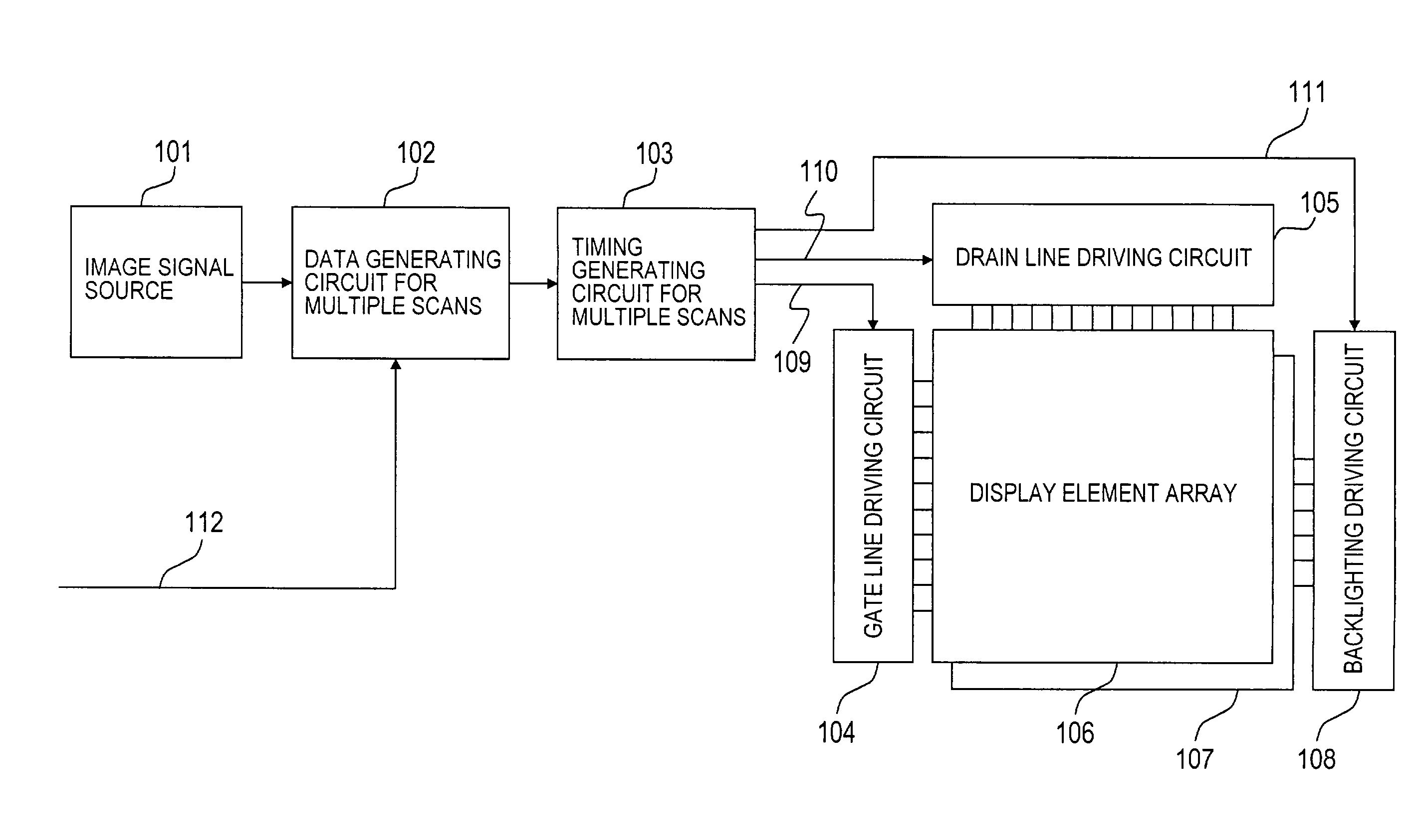
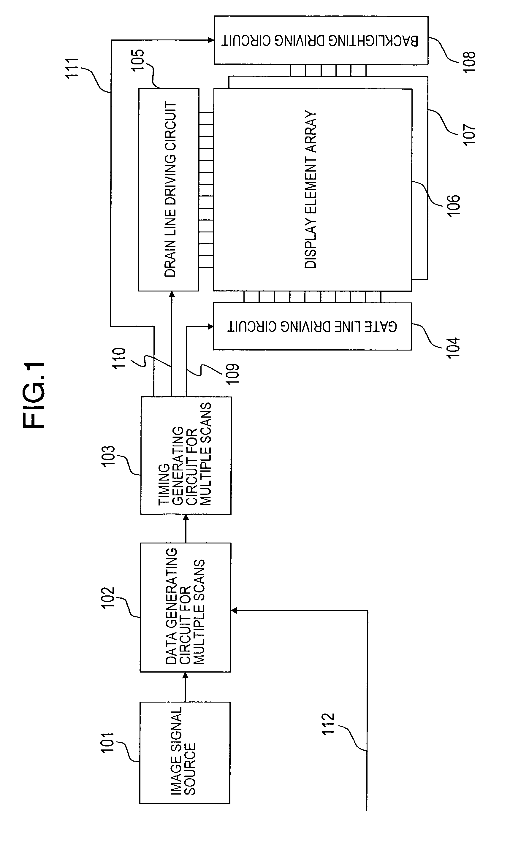
[0099]FIG. 1 is a system block diagram of a liquid crystal display device, which will be described according to this embodiment.

[0100]FIG. 1 includes an image signal source 101, data generating circuit 102 for multiple scans, and a timing generating circuit 103 for multiple scans. The image signal source 101 generates and reads image signals for personal computers and televisions. The data generating circuit 102 for multiple scans has an interface, which can receive video in different format from the image signal source 101, and generates data to be screen-scanned multiple times in one frame based on the video signals. The timing generating circuit 103 for multiple scans generates timing for scanning screens multiple times in one frame. Furthermore, FIG. 1 includes a liquid crystal display element array (display panel) 106, a gate line drive circuit 104, and a drain line drive circuit 105. In the liquid crysta...

sixth example

[0157]FIG. 45 shows an example of scanning at the double frame frequency 120 Hz, which is obtained by the two-line synchronous writing and the two-line interlace scanning. In this example, each of screens is divided into the right half and left half portions. One of the portions is used for image writing, and the other half portion is used for blanking data writing. The image writing and the blanking data writing are performed at 120 Hz alternately. Unlike the black display on the entire screen in the first example, the spatial modulation is performed on the black display in the sixth example. Thus, the performance for moving image display is maintained while the flicker can be reduced.

[0158]Incidentally, the spatial modulation may be performed for the black vertical stripe display having horizontal four divisions and horizontal six divisions, respectively, in one screen. Also in this case, the black vertical stripe display is switched at 120 Hz. Thus, the flicker can be reduced mor...

seventh example

[0159]FIG. 46 shows an example of scanning at the double frame frequency 120 Hz, which is obtained by the two-line synchronous writing and the two-line interlace scanning. In this example, each of screens is divided into vertical and horizontal four portions. A pair of the diagonal portions is used for image writing, and the other pair of the diagonal portions is used for blanking data writing. The image writing and the blanking data writing are performed at 120 Hz alternately. Unlike the black display on the entire screen in the first example, the spatial modulation is performed on the black display. Thus, the performance for moving image display is maintained while the flicker can be reduced.

[0160]Incidentally, the spatial modulation may be performed for the black checker pattern display having total of sixteen divisions each having vertical and horizontal four divisions or the black checker pattern display having total of thirty-six divisions each having vertical and horizontal s...


PUM

PropertyMeasurementUnit
aspect ratioaaaaaaaaaa

Abstract

A matrix-type display device includes a data generating circuit 102 for multiple scans for inserting blanking data to image data for one frame period of an image, and a timing controlling circuit 103 for multiple scans for generating clocks used by a gate line drive circuit 104 for scanning lines of a display element array 107 such that the image data and the blanking data can be displayed in one frame period. Here, the gate line drive circuit 104 simultaneously scans multiple lines adjacent to each other as a bundle. According to this configuration, the larger and more complicated construction can be suppressed, which can also suppress the image deterioration due to blurred moving picture.

Description

BACKGROUND OF THE INVENTION[0001]1. Field of the Invention[0002]The present invention relates to a matrix-type display device having display elements such as amorphous silicon liquid crystal, polysilicon liquid crystal, light emitting diode or organic EL, and particularly to a display device for performing blanking processing.[0003]2. Description of the Related Art[0004]Japanese Unexamined Patent Application Publication No. 11-109921 is a technology of the related art. According to the technology of the related art, one liquid crystal display panel is divided into tow upper and lower pixel arrays. Data line drive circuits are provided to the divided pixel arrays, respectively. One gate line for each of the upper and lower pixel arrays, that is, a total of two gate lines for the upper and the lower gate lines are selected. Two of the upper and lower divided display areas are dual-scanned by the respective drive circuits. During the dual scanning, a blanking image (black image) is ins...

Claims


Application Information

Patent Timeline
Patent Type & Authority Patents(United States)
IPC IPC(8): G09G3/36G09G5/10G02F1/133G09G3/20G09G3/34G09G5/00
CPCG09G3/342G09G3/3648G09G5/005G09G5/006G09G3/20G09G2370/04G09G3/3406G09G3/3614G09G3/3696G09G2310/0205G09G2310/0221G09G2310/0232G09G2310/024G09G2310/027G09G2310/061G09G2310/08G09G2320/0247G09G2320/0252G09G2320/0261G09G2320/0633G09G2320/064G09G2320/10G09G2340/0407G09G2340/0414G09G2340/0442G09G2360/18G09G3/2018G02F1/133
Inventor KAWABE, KAZUYOSHIHIRAKATA, JUNICHI
Owner PANASONIC LIQUID CRYSTAL DISPLAY CO LTD
Why Eureka
Try Eureka