
Coupling circuit arrangement for data communication over power lines
a technology of data communication and coupling circuit, which is applied in the direction of transmission, transmission system, automatic controller, etc., can solve the problems of not being practical, not being able to reduce the physical dimensions and cost of the coupling transformer, and being considered potentially dangerous to li
- Summary
- Abstract
- Description
- Claims
- Application Information
AI Technical Summary
Benefits of technology
Problems solved by technology
Method used
Image

Examples
Embodiment Construction
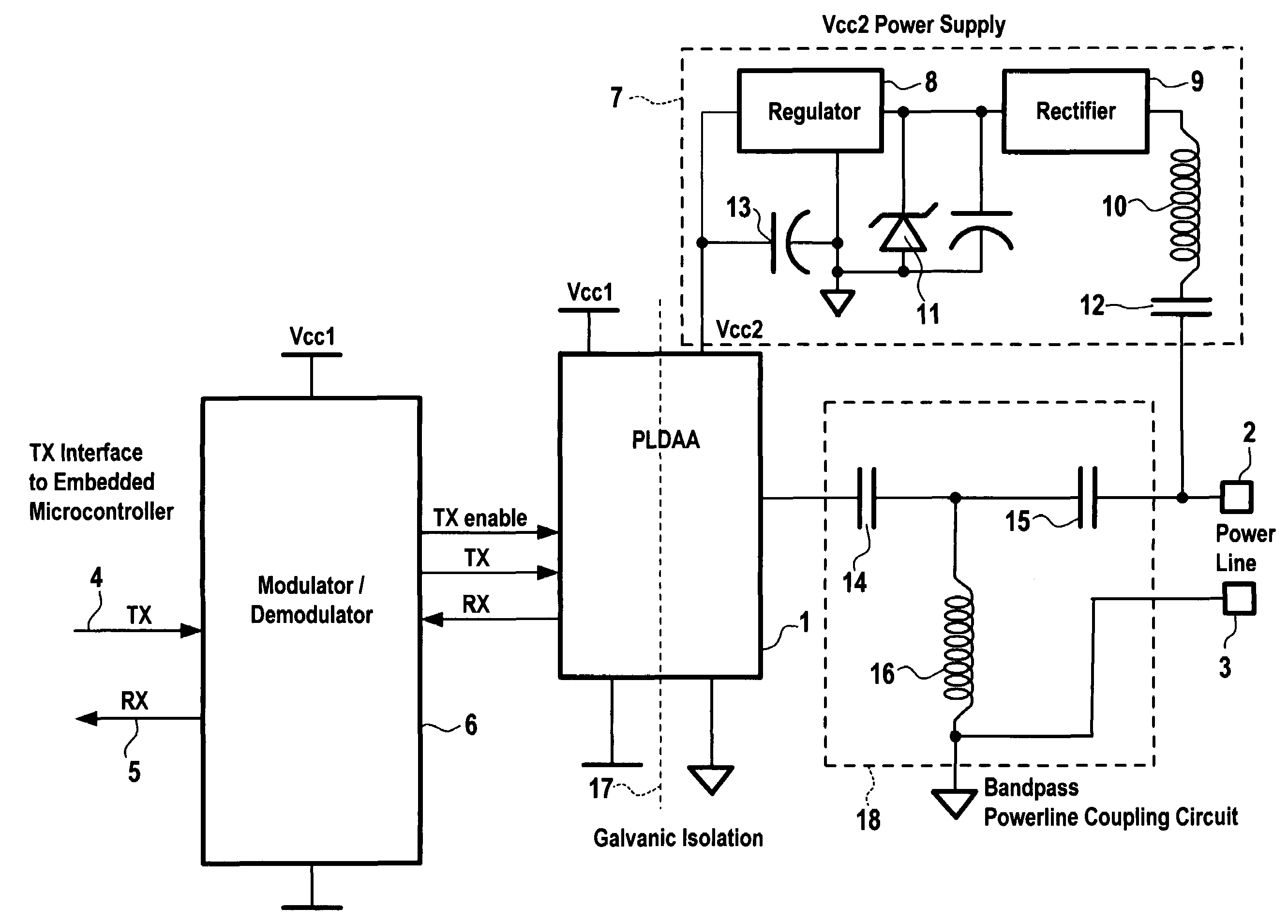
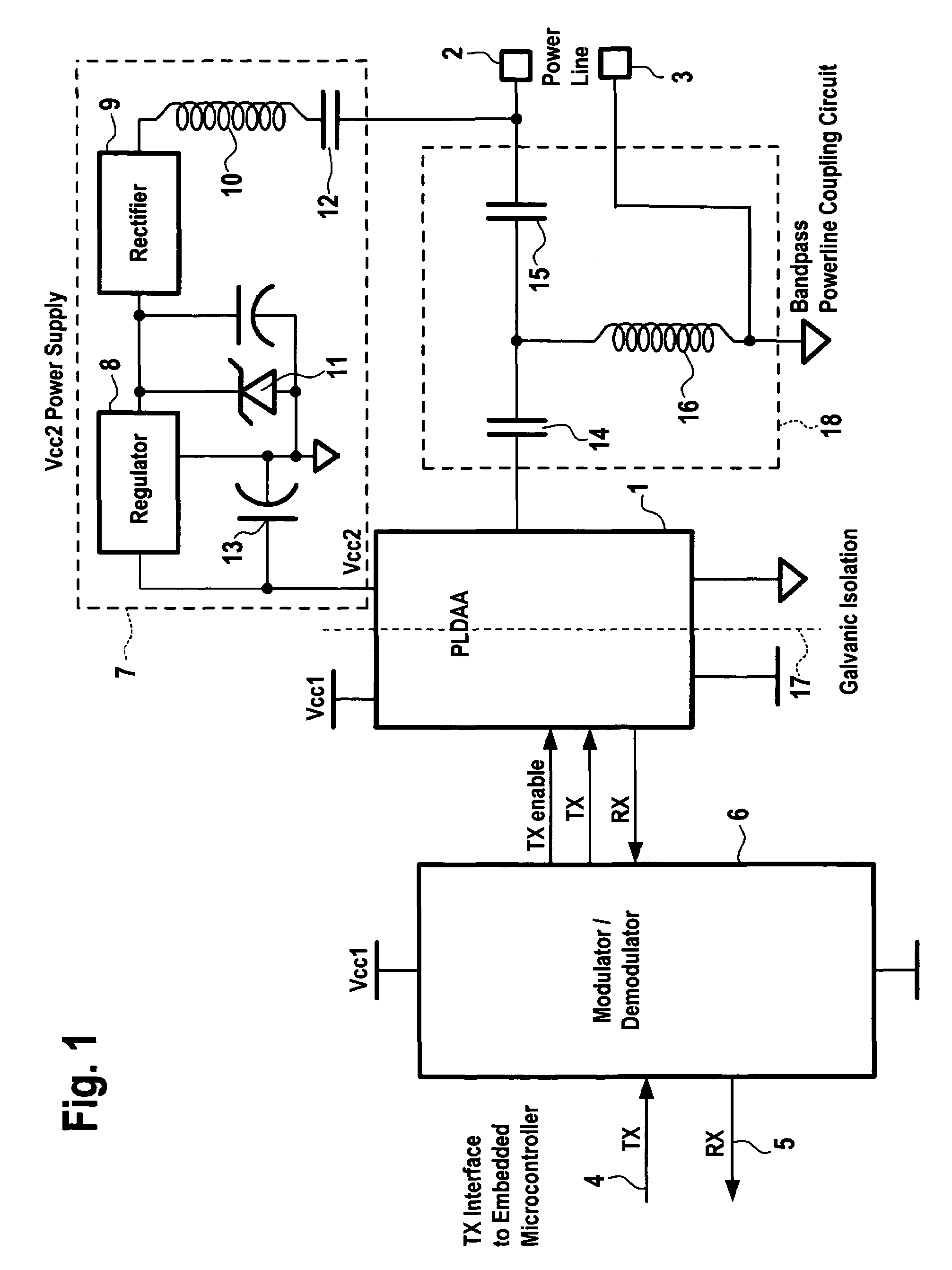
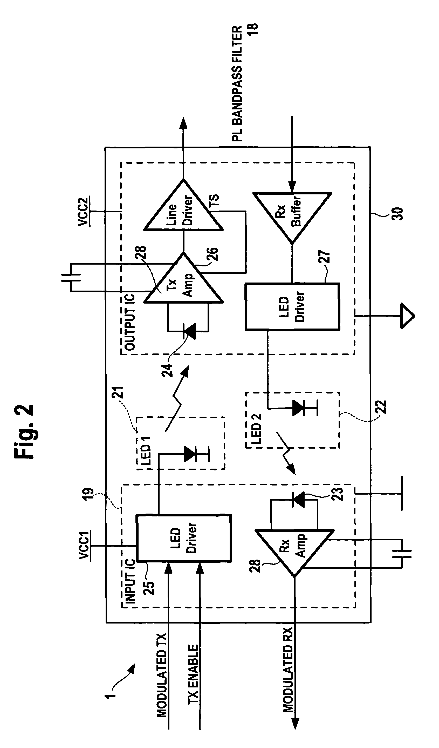
[0030]Referring to FIG. 1, the power line over which data are transmitted is indicated with terminals 2,3. The data which are to be coupled into the power line are supplied from external circuitry (not shown) on a transmit line 4 and the data which have been transmitted over the power line and which are to be supplied to subsequent data processing circuitry are supplied on a receive line 5. The letters TX in the drawings are used for “transmit” and the letters RX are used for “receive”. The direction of signal flow is indicated with arrows. The input TX signal on line 4 is supplied to a modulator / demodulator circuit 6, and the modulated output signal is supplied to a data access arrangement 1. The dotted line 17 in block 1 represents the galvanic isolation between the input and output circuitry. The data access arrangement 1 forms an important part of the invention and will be described in more detail below.
[0031]The data access arrangement 1 is connected to a power supply circuit 7...
PUM
 Abstract
Description
Claims
Application Information