Multiprotocol RFID reader

a radiofrequency identification and transponder technology, applied in the field of interrogation of radiofrequency identification transponders, can solve the problems of increasing the physical size and weight of the reader, unsatisfactory, and the rfid system presenting challenges for conventional rfid readers, and achieves low cost, high sensitivity, and small size

Inactive Publication Date: 2007-03-27
WJ COMM
View PDF35 Cites 89 Cited by
  • Summary
  • Abstract
  • Description
  • Claims
  • Application Information

AI Technical Summary

Benefits of technology

[0010]The present invention includes an RFID reader for interrogating passive RFID tags which preferably combines small size, high sensitivity, and low cost. In one embodiment of the present invention, the reader is in a standard PC card format and includes a crystal oscillator, a frequency synthesizer referencing a clock signal from the crystal oscillator, and a PC card interface and a controller both operating according to the same clock signal from the crystal oscillator. Thus, a single crystal oscillator is used to provide clock signals to the frequency synthesizer, the PC card interface and the controller. Therefore, digital transitions in the PC card interface and the controller are synchronized with the frequency synthesizer and do not interfere with the accuracy of synthesis. Using the same crystal oscillator also greatly reduces the disturbances on the transmit functions of the reader and spurious transmissions caused by the operations of the PC card interface and the controller.

Problems solved by technology

In a conventional homodyne reader, such as the one described in U.S. Pat. No. 2,114,971, two separate decoupled antennas for transmission (TX) and reception (RX) are used, resulting in increased physical size and weight of the reader, and are thus not desirable.
Recent developments in RFID systems present challenges for conventional RFID readers.
Each of these classes has its own power consumption, reliability, and bandwidth requirements.
Other challenging issues arise from interrogating passive RFID tags because the same signal used to communicate with the tags has to be used to power the tags.
The amount of information that may be sent from a reader to a tag is thus limited by these limitations on modulation.
Furthermore, RFID readers have not been made in a PC Card format so that it can be integrated in handheld, portable or laptop computers to read from and write to RFID tags.
A PC Card RFID reader, however, presents other challenges because RF components of a conventional reader cannot fit in a small PC card housing and the operation of a PC interface may generate spurs in the transmit channel of the reader, resulting in spurious emissions from the reader that do not comply with regulatory requirements from the government.

Method used


Image

  • Multiprotocol RFID reader
  • Multiprotocol RFID reader
  • Multiprotocol RFID reader

Examples


Embodiment Construction

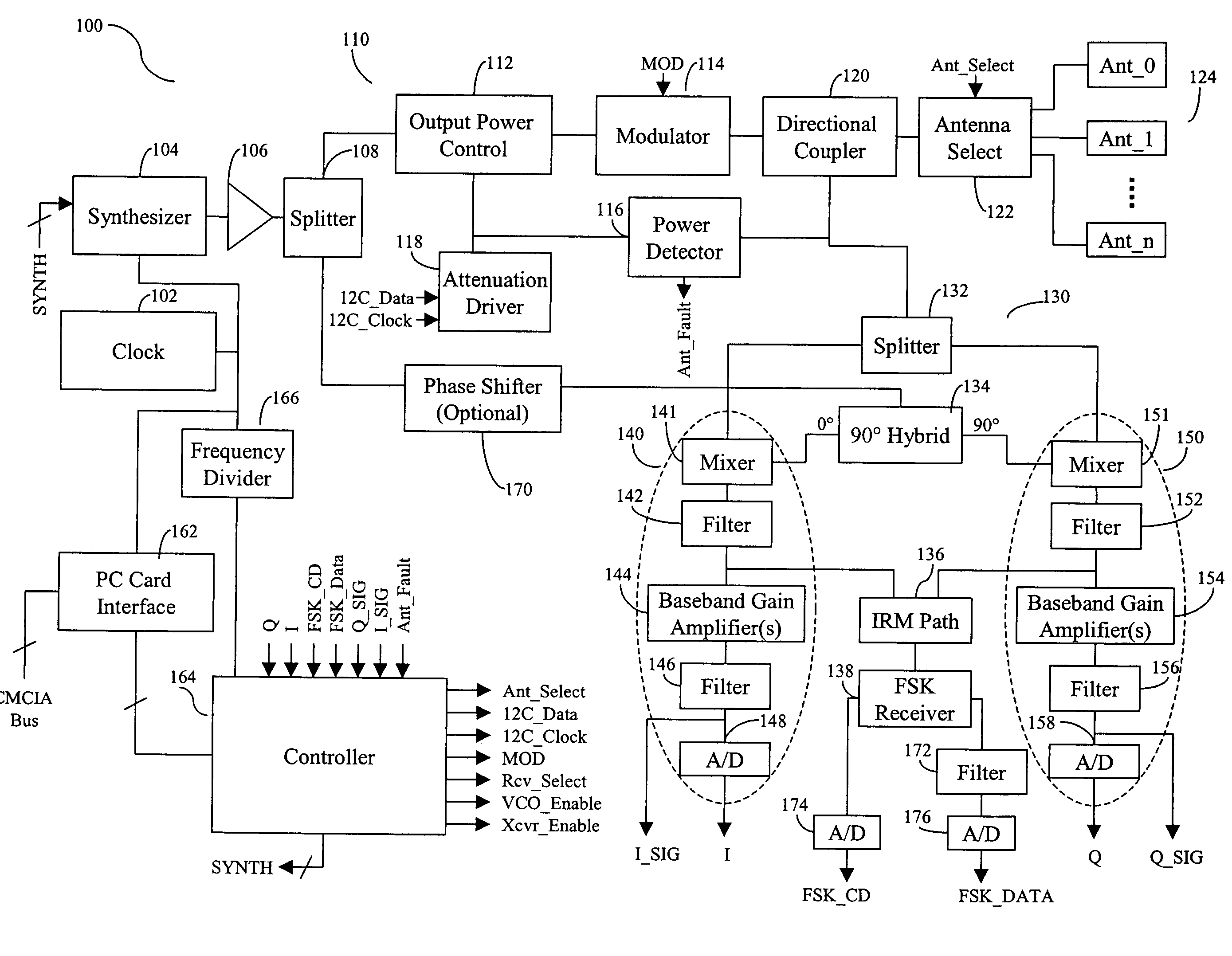
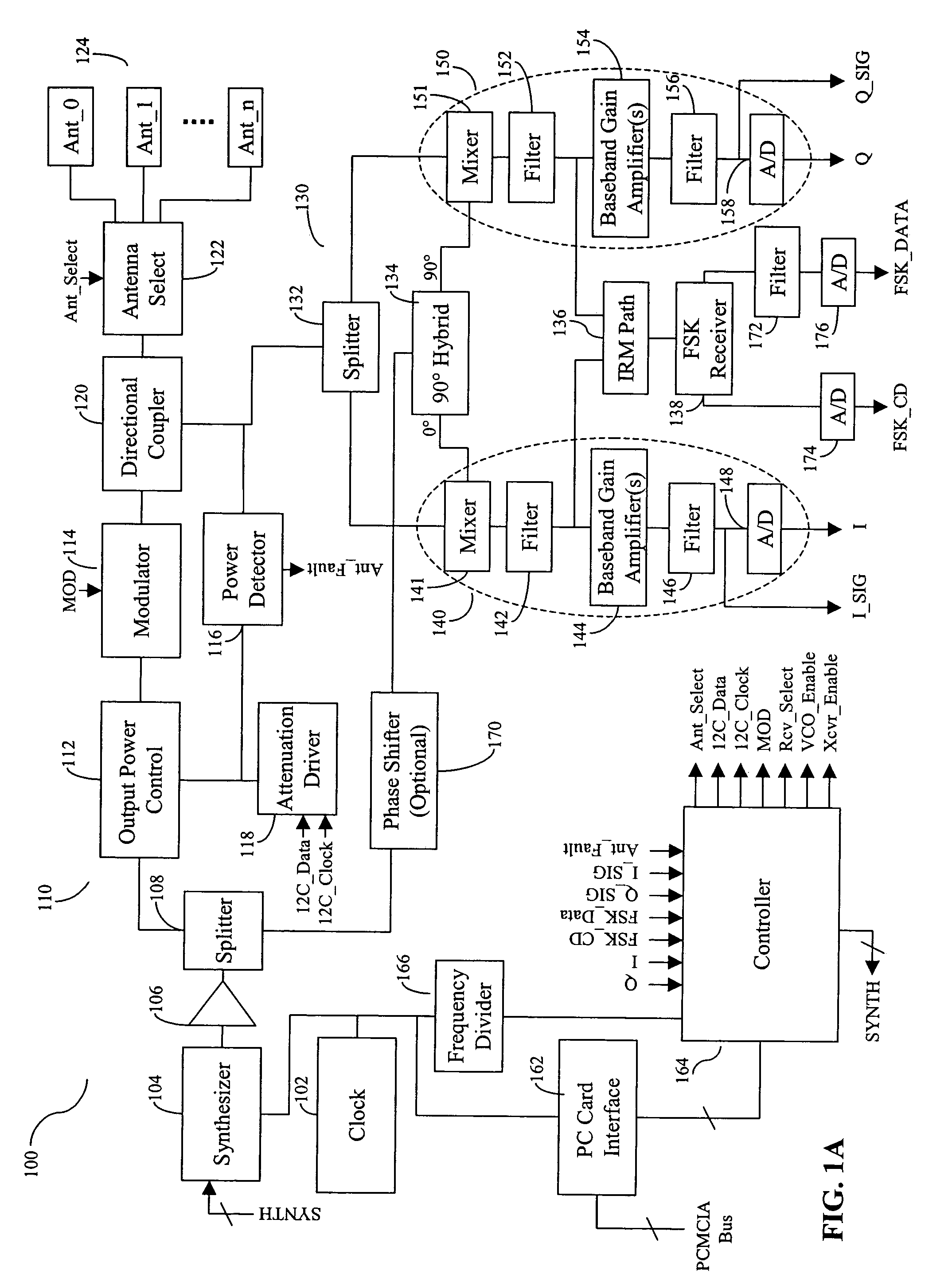
[0051]FIG. 1A is a block diagram of an RFID reader 100 according to one embodiment of the present invention. As shown in FIG. 1A, reader 100 includes a crystal oscillator 102 configured to generate a clock signal, and a frequency synthesizer 104 configured to generate a continuous wave (CW) signal referencing the clock signal. Reader 100 further includes a local oscillator (LO) buffer amplifier 106 coupled to synthesizer 104 and configured to amplify the CW signal. LO buffer amplifier 106 also protects the synthesizer from disturbances created from other parts of reader 100. LO buffer amplifier 106 may be implemented using conventional means.

[0052]Reader 100 further includes a transmit (TX) chain 110 configured to form and transmit a transmit (TX) signal for interrogating a tag, and a receive (RX) chain 130 configured to receive an RF signal from the tag, and to generate a plurality of output signals from the RF signal. TX chain 110 includes an output power control module 112, a mod...


PUM


Abstract

An RFID reader accessible thorough a personal computer and includes a PC card interface and a controller both operating according to clock signals from a crystal oscillator. The RFID reader further includes a linearized power amplifier modulator in a transmit path, a receive chain capable of demodulating EPCglobal Class_1 and Class_0 signals from RFID tags, and an integrated switching device for selecting one of a plurality of antenna for transmitting or receiving RF signals.

Description

CROSS REFERENCE TO RELATED APPLICATIONS[0001]The present application claims priority to U.S. Provisional Patent Application No. 60 / 533,970 filed on Dec. 31, 2003, and U.S. Provisional Patent Application No. 60 / 605,214 filed on Aug. 27, 2004, the entire disclosure of each of which is hereby incorporated by reference in its entirety.[0002]The present application is related to co-pending U.S. patent application Ser. No. 11 / 021,302 entitled “A Linearized Power Amplifier Modulator” and U.S. patent application Ser. No. 11 / 021,539 entitled “Integrated Switching Device for Routing Radio Frequency Signals”, both filed on Dec. 23, 2004, the entire disclosure of each of which is hereby incorporated by reference in its entirety.FIELD OF THE INVENTION[0003]The present invention relates in general to interrogation of radio-frequency identification (RFID) transponders, and particularly to an advanced RFID reader compatible with a PC card standard and with improved sensitivity, reduced spurs, and m...

Claims


Application Information

Patent Timeline
Patent Type & Authority Patents(United States)
IPC IPC(8): H04B1/40H04B1/59G06K7/00G06K7/10G08B13/14
CPCG06K7/0008G06K7/10128G06K19/07741G06K7/10346G06K7/10316
Inventor BELLANTONI, JOHN VINCENT
Owner WJ COMM
Why Eureka
Try Eureka