Baton holder

a baton and holder technology, applied in the field of baton holders, can solve the problems of not being able to place the baton laterally in the radial direction, being susceptible to higher manufacturing costs, and being able to easily be unauthorized to act, and achieve the effect of convenient and comfortable operation

Inactive Publication Date: 2007-05-01
KOSTAL BRETISLAV +1
View PDF5 Cites 8 Cited by
  • Summary
  • Abstract
  • Description
  • Claims
  • Application Information

AI Technical Summary

Benefits of technology

[0005]The primary object of the invention is to provide a safe holding of the baton in both retracted and expanded configuration, whereby the position of the baton in the holder is automatically fixed when a baton handle is inserted into the holder. Another object of the invention is to enable the placing and removal of the expanded baton not only along the longitudinal axis of the holder but also laterally in radial direction. Still another object of the invention is that the holder includes minimum construction parts and its operation is easy and comfortable.

Problems solved by technology

Before using the baton first the cover flap is to be released so that the action of the officer is delayed, what may cause that he can be exposed to a sudden unauthorized action of an attacker.
The mere insertion of the baton into the holder interior passage does not provide sufficient grip of the baton by the holder and therefore additional hand operated means shall be used to this effect.
Moreover, the baton holder shows a number of components and is thus susceptible to higher manufacturing costs and rather complicated operating.
Moreover, the placing of the baton into the housing laterally in radial direction is impossible and the baton may be inserted in the holder only from its upper end along the longitudinal axis of the holder.

Method used


Image

  • Baton holder
  • Baton holder
  • Baton holder

Examples


Embodiment Construction

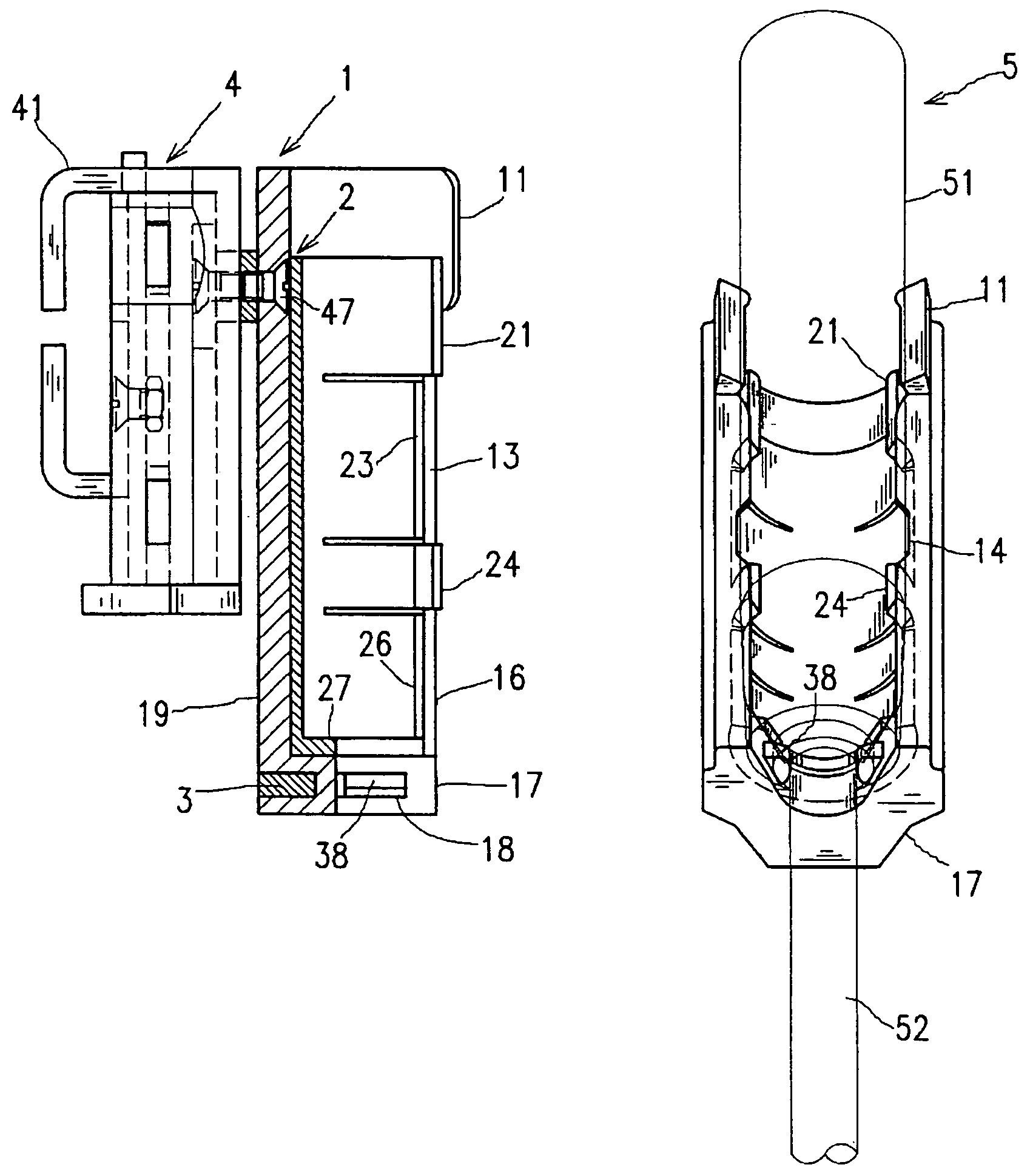
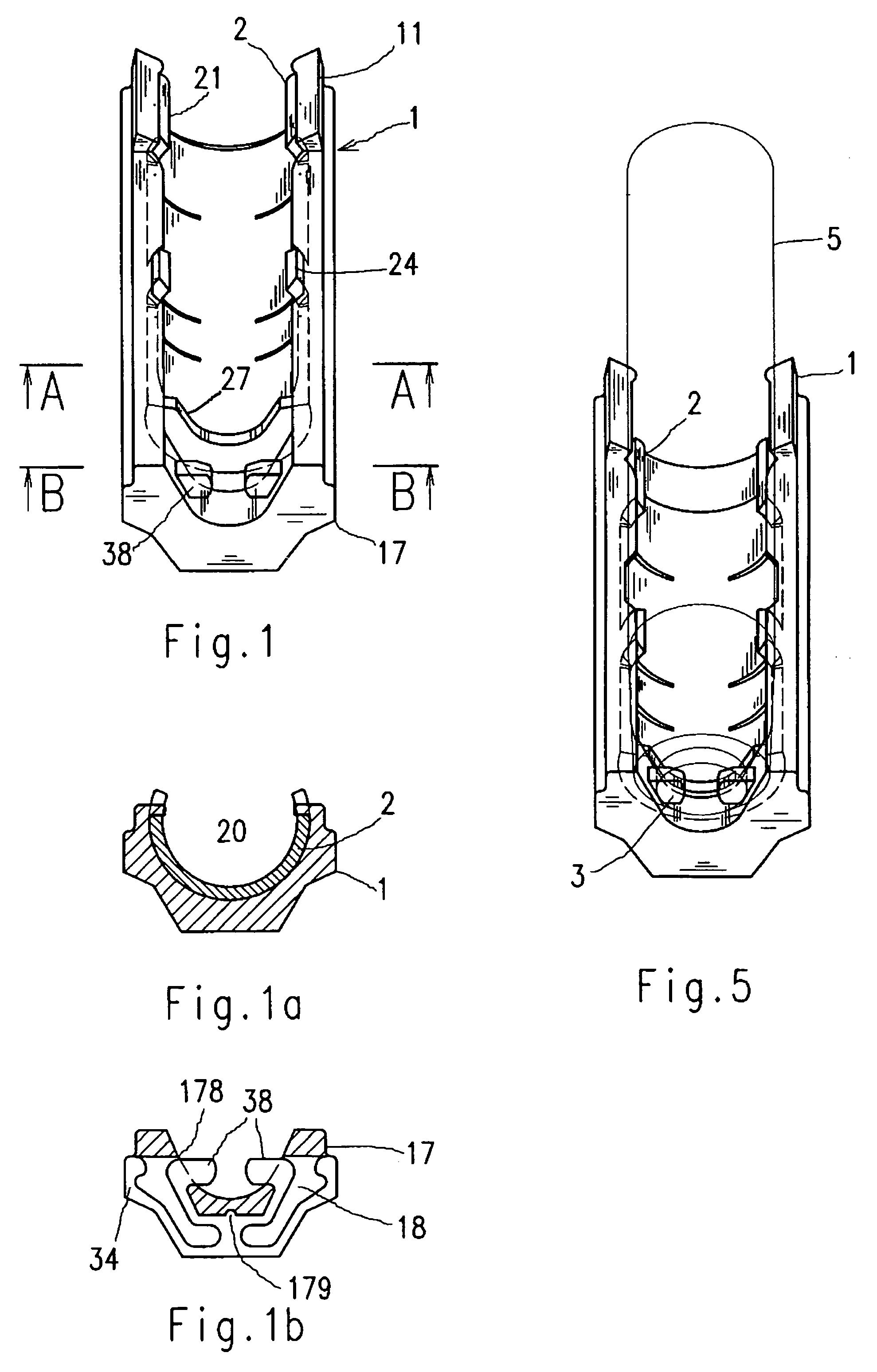
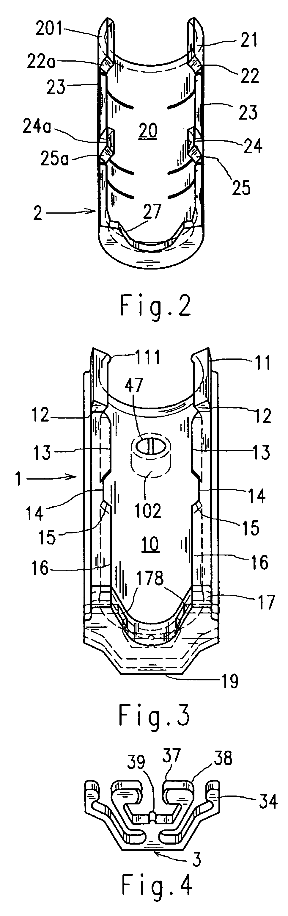
[0022]As shown in FIG. 1 to FIG. 4, a baton holder according to the invention consists substantially of three major parts: a trough-like body 1, a cradle mounted for longitudinal motion in the body 1 and a clamp 3. The holder is assigned to hold firmly a baton 5 having a handle 51 and a telescopic shaft 52, the outer lines of which are schematically illustrated in FIGS. 5 and 7.

[0023]As shown in more details in FIG. 3, the body 1 takes a shape of a trough with a partially plain back surface 19 and has an inner wall substantially in the form of a cylindrical surface 10. The longitudinal margins of the body 1 are provided by opposite situated edges 13 and 16 separated by cut-outs 14. The side walls 12, 15 of the edges 13, 16 are slanted. At its upper end the body 1 carries a collar 11 with a shoulder 111 and at its lower end the body is provided with a foot 17 (FIG. 6) extending over the inner wall of the body 1. The foot 17 has at its outer side a slot 18 and in the slot 18 two oppos...


PUM


Abstract

A baton holder consisting of at least one portion comprising the means adjustable into an opened position for insertion in and withdrawing of a baton from the holder and into a closed position for fixing the baton in the holder where the holder comprises an outer portion and an inner portion mounted for longitudinally motion in the outer portion along the longitudinal axis of the holder whereby the outer portion and the inner portion are provided by mutually cooperating elements (21, 24; 11, 14) permitting the inner portion to open in the opened position of the holder and to close and fix the baton body in the closed position of the holder. The inner portion consists of a cradle (2) having a generally opened cylindrical outer surface (201) and a cylindrical inner surface (20) and the outer portion consists of an opened elongated body (1) having a generally internal cylindrical surface (10) to support said cradle (2).

Description

FIELD OF THE INVENTION[0001]The invention relates to a baton holder consisting of at least one portion comprising means adjustable into an opened position for insertion in and withdrawing of a baton from the holder and into a closed position for fixing the baton in the holder. The holder is adapted for holding the baton on a belt of law enforcement personnel, police officers etc.DESCRIPTION OF THE PRIOR ART[0002]Batons represent one of conventionally used devises of the law enforcement personnel. At this time the preferred types of batons are expandable batons having a handle adapted for receiving a telescopic shaft, whereby the dimensions of the handle and the shaft are substantially standardized. Nevertheless, baton holders may occur in various types and with variety of functions. The holders are secured to the belt of the respective person by means of a clip forming a part of the holder or mounted on the holder and optionally releasable therefrom.[0003]The U.S. Pat. No. 5,263,619...

Claims


Application Information

Patent Timeline
Patent Type & Authority Patents(United States)
IPC IPC(8): A01K97/04A45F5/02A45F5/14
CPCA45F5/02A45F5/14A45F2200/0566
Inventor KOSTAL, BRETISLAVKUPA, VLADIMIR
Owner KOSTAL BRETISLAV
Why Eureka
Try Eureka