Portable splittable fixture for rotational welding of pipes

A rotary welding and portable technology, which is applied in welding equipment, auxiliary welding equipment, workpiece clamping device, etc., can solve the problems of inability to realize portable use, inability to adjust the angle of the device, and the device is too large, so as to achieve comfortable operation and low weight. Light, clamping way unique effect

Active Publication Date: 2018-04-24
章雪霞
View PDF6 Cites 8 Cited by
  • Summary
  • Abstract
  • Description
  • Claims
  • Application Information

AI Technical Summary

Problems solved by technology

However, the overall device of this kind of equipment is too large and can only be used in designated places, and cannot be used portablely, and the device cannot realize angle adjustment

Method used


Image

  • Portable splittable fixture for rotational welding of pipes
  • Portable splittable fixture for rotational welding of pipes
  • Portable splittable fixture for rotational welding of pipes

Examples


specific Embodiment approach 1

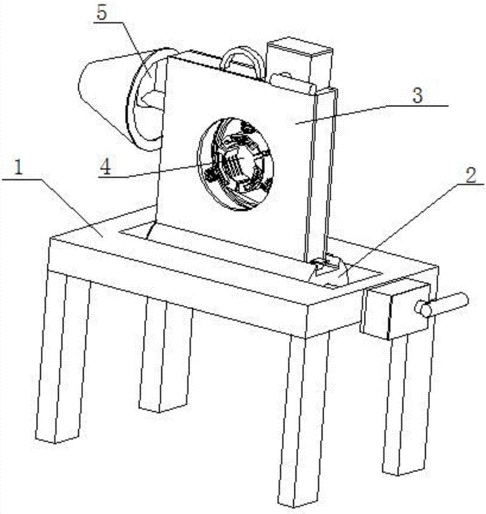
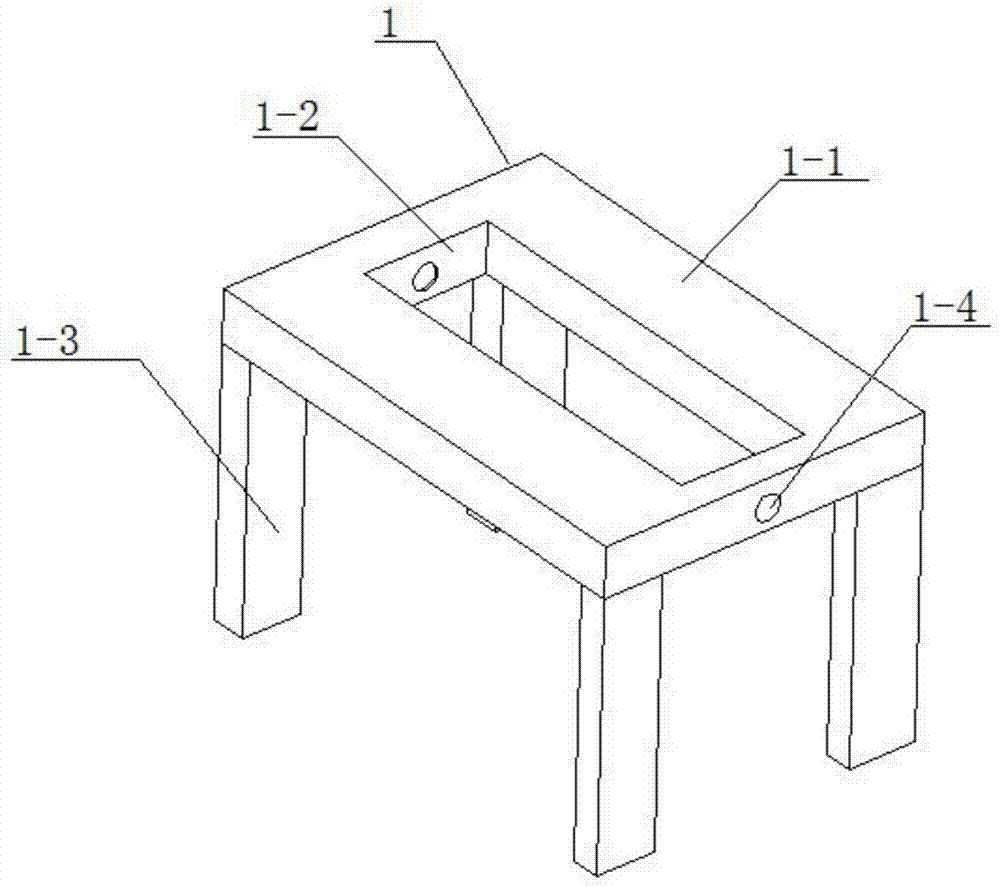
[0029] Such as Figure 1 to Figure 9 As shown, a portable and detachable fixture for rotary welding pipe fittings, the fixed bottom table 1 includes a table board 1-1, a central rectangular groove 1-2, table legs 1-3 and a shaft rotating round hole 1-4, The central rectangular groove 1-2 runs through the center of the table board 1-1 up and down, and there are four table legs 1-3, and the four table legs 1-3 are respectively fixedly connected to the four bottom corners of the lower ends of the table legs 1-3, The shaft rotation circular hole 1-4 is arranged on the right end of the table board 1-1, and the shaft rotation circular hole 1-4 communicates with the central rectangular groove 1-2. The adjustment of the angle of rotation of the fixture structure 4 is realized by the sliding of the fixture structure 4 on the fixture fixing frame 3, and the adjustment of the vertical angle of the fixture structure 4 is realized by the sliding connection of the fixture fixing frame 3 on ...

specific Embodiment approach 2

[0030] Such as Figure 1 to Figure 9 As shown, this embodiment further explains Embodiment 1. The fixed bottom table 1 includes a table plate 1-1, a central rectangular groove 1-2, table legs 1-3 and a shaft rotation hole 1-4, and the central rectangular The groove 1-2 runs through the center of the table board 1-1 up and down, and there are four table legs 1-3, and the four table legs 1-3 are respectively fixedly connected to the four bottom corners of the lower ends of the table legs 1-3. The rotating circular hole 1-4 is arranged on the right end of the table board 1-1, and the axis rotating circular hole 1-4 communicates with the central rectangular groove 1-2.

specific Embodiment approach 3

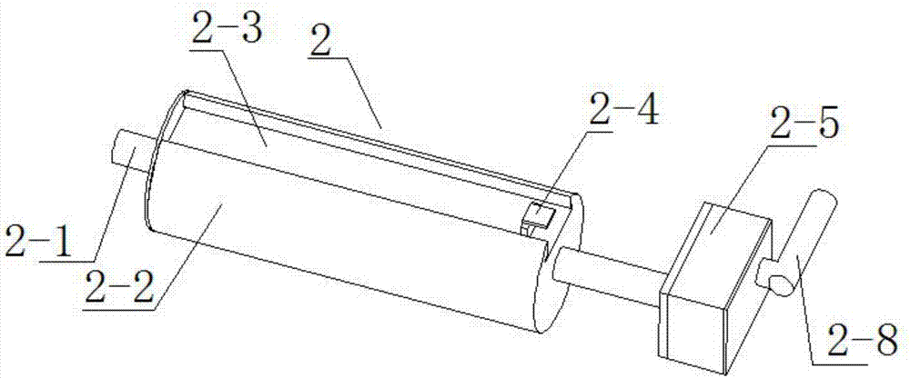
[0031] Such as Figure 1 to Figure 9As shown, this embodiment further explains Embodiment 2. The tea transfer structure 2 includes a rotating shaft 2-1, a rotating round block 2-2, a sliding rectangular slot 2-3, a rectangular inserting block 2-4, and a rotating adjustment Rectangular frame 2-5, driven circular gear 2-6, driving circular gear 2-7 and hand rocker 2-8, rotating shaft 2-1 is rotationally connected to the inner wall of central rectangular groove 1-2, rotating shaft 2-1 is clearance fit The shaft rotates the round hole 1-4, the rotating round block 2-2 is fixedly connected on the rotating shaft 2-1, the sliding rectangular slot 2-3 is arranged on the rotating round block 2-2, and the front and rear ends of the sliding rectangular slot 2-3 are respectively A chute is provided, a rectangular slot is provided on the sliding rectangular slot 2-3, the gap between the rectangular insert 2-4 matches the rectangular slot, and the left end of the rotating and adjusting rect...


PUM


Abstract

The invention relates to the field of fixtures, more in particular to a portable splittable fixture for rotational welding of pipes, comprising a fixed base table, a rotational adjusting structure, afixture fixing clamp, a fixture structure and a conical driving ejector structure; the rotational adjusting structure is rotationally connected inside the fixed base table; the fixture fixing frame isslidably connected in the rotational adjusting structure; the fixture structure is slidably connected inside the fixture fixing frame; the conical driving ejector structure is fixedly connected to the fixture fixing frame. The portable splittable fixture for rotational welding of pipes has the advantages that the fixture is convenient to split, light in weight, small in size and convenient to carry, is suitable for use in small spaces, has a unique and effective clamping mode, has no need for manual adjustment according the size of a pipe, has adjustable application angle, can rotate, and iscomfortable for operators to operate.

Description

technical field [0001] The invention relates to the field of fixtures, in particular to a portable and detachable fixture for spin-welded pipe fittings. Background technique [0002] A clamp is a fixing tool used to fix equipment and devices during routine mechanical maintenance or installation. Patent No. CN201521021674.6 discloses a fixture for long and thin-walled pipe fittings, which belongs to the field of fixture technology. It includes a base, the middle part of the base is fixed with a pipe body clamp, the two ends of the base are fixed with pipe end clamps, the pipe body clamp includes a clamp body, and the inner wall of the clamp body is a tapered surface structure. An open elastic sleeve is arranged in the clamp body, and the end of the clamp body is threadedly connected with a lock nut, and the lock nut locks the open elastic sleeve in the clamp body. The above-mentioned fixture for long and thin-walled pipe fittings has the advantages of simple structure, reli...

Claims


Application Information

Patent Timeline
Patent Type & Authority Applications(China)
IPC IPC(8): B23K37/053B25B11/00
Inventor 章雪霞
Owner 章雪霞
Why Eureka
Try Eureka