Locking device having flange seal

a technology of locking device and flange seal, which is applied in the direction of padlocks, towing devices, building locks, etc., can solve the problems of prone to false locking, easy to fall off the locking head during use, and disadvantageous use, and achieves convenient sealing and simple construction.

Inactive Publication Date: 2007-06-05
WYERS PHILIP W
View PDF25 Cites 30 Cited by
  • Summary
  • Abstract
  • Description
  • Claims
  • Application Information

AI Technical Summary

Benefits of technology

[0009]It is an object of the present invention to provide a new and useful locking device that is simple in construction and yet which provides a convenient seal between a locking head and the shackle.
[0011]Still a further object of the present invention is to provide a locking device which is aesthetically pleasing yet which provides a convenient and simple seal to help insulate the locking mechanism against intrusion of foreign substances while in use.
[0012]Still a further object of the present invention is to provide an old-type locking structure having a pleasing, symmetrical appearance.
[0017]If desired, a stop portion cover may also be provided according to the present invention. Here, the stop portion cover may substantially encase the stop portion. This stop portion cover may be formed of a stiff yet resilient material. If desired, the stop portion may have a radially inwardly projecting flange, that may be formed by an annular washer that snap locks onto this stop cover portion. This flange then extends alongside the inner stop face and, along with the flange of the head cove, can provide a resilient bumper to help reduce rattling of a hitch pin when used with a hitch bar and hitch receiver.

Problems solved by technology

The bulky nature of this lock head design, however, makes it disadvantageous in use where only limited space is available.
In addition, where the locking pin is spring loaded, the locking structure of Holden is prone to false locking, that is, the engagement of the locking head and shackle without an actual locked state occurring.
Thus, the locking head may fall off during use.
These types of locks, however, tend to be inconvenient and cumbersome to use due to the threaded nature of their locked mechanisms.
The inconvenience and difficulty of threaded lock systems is compounded when the lock is located in tight or difficult to access areas.
Further, the threaded screw locks are especially prone to corrosion and seizure due to the small dimensioning of the threads.
The majority of the locking structures described in the prior art fail to employ suitable seals or other structures, such as caps or protective devices to limit access of unwanted substances such as dirt and moisture into the keyway or into the locking region.
While the Chang patent does address the importance of limiting the access of dirt and moisture into the locked mechanism, the solution offered in the Chang patent has some drawbacks.
Thus, the seal can become damaged due to the snagging or rubbing of the seal against the aligned holes.

Method used


Image

  • Locking device having flange seal
  • Locking device having flange seal
  • Locking device having flange seal

Examples


Embodiment Construction

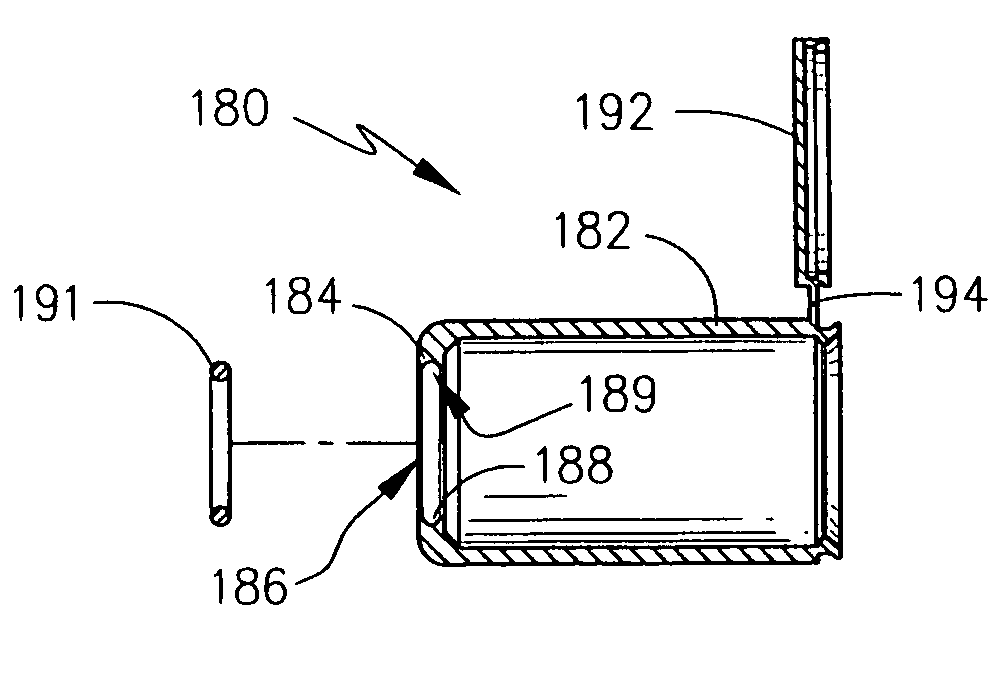
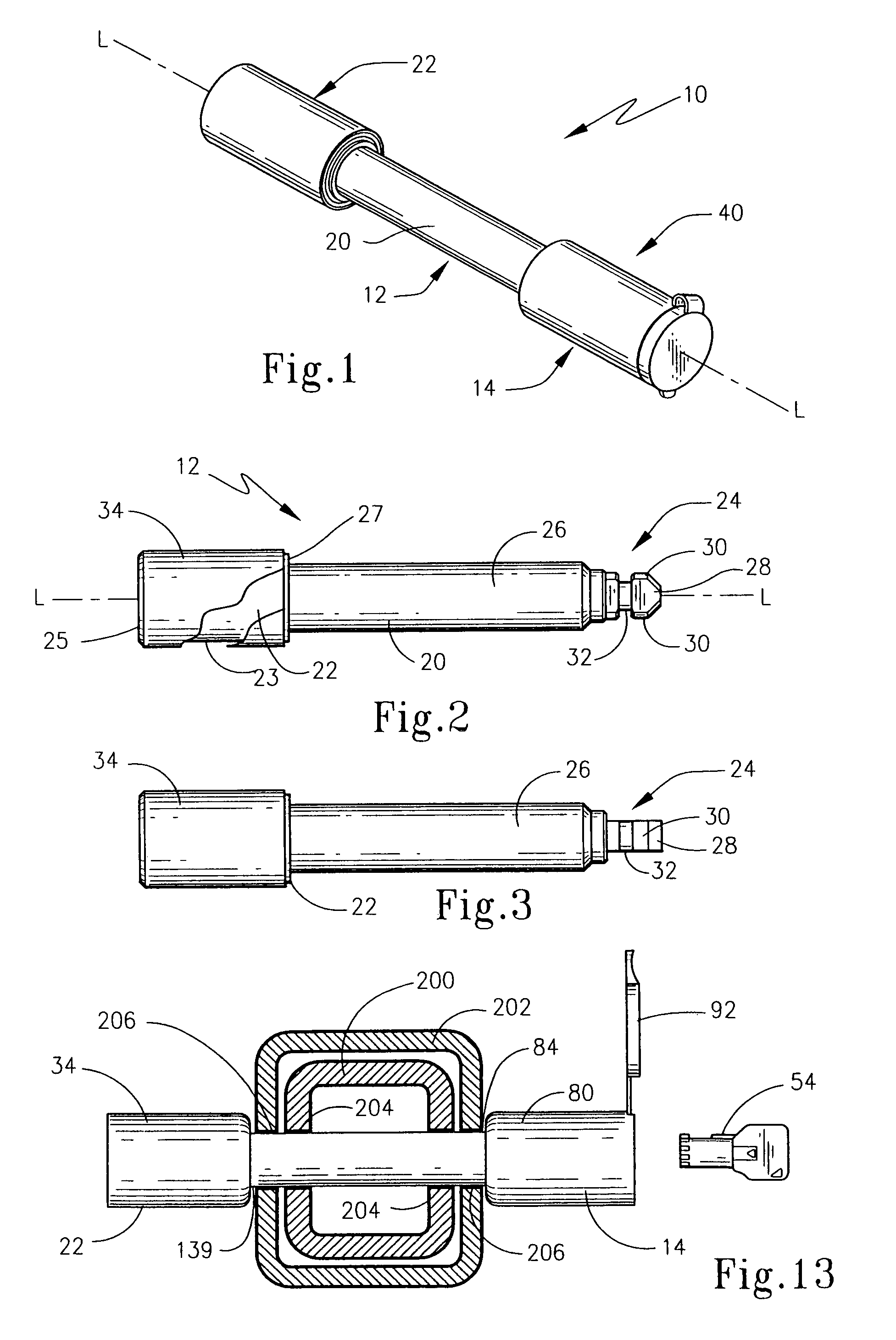
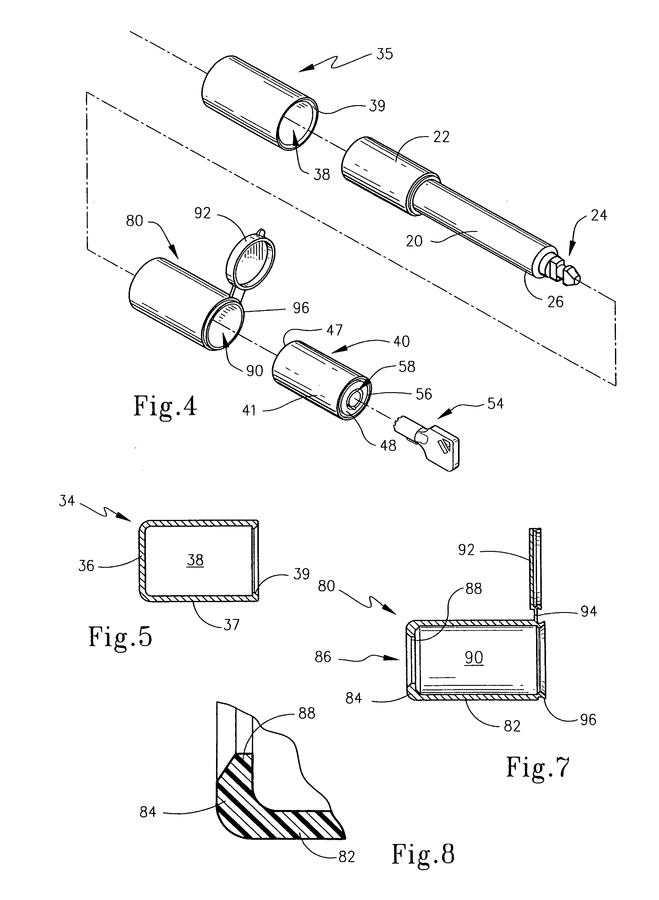
[0033]The present invention is broadly directed to a locking device that is adapted to secure objects together. This device is particularly constructed so as to provide a seal between the locking head and a shank portion of the shackle. While the present invention may be employed with a variety of locking devices, it particularly concerns a locking device in the form of a pin type-locking device that is used to secure two objects together and is specifically depicted as a hitch pin that may be used to secure a hitch receiver to a hitch bar as is the common practice in towing applications. Moreover, while the present invention is described with respect to a key operable locking device, it should be understood that the invention is not limited to key operable locking devices, but the inventive concepts herein may be employed with combination-type locking mechanisms.

[0034]For illustrative purposes, the present invention is described for a locking device employing a locking mechanism su...


PUM


Abstract

A locking device includes a shackle member that includes an elongated shank portion, a stop portion on a first end and a latch portion on a second end. A locking head includes a locking mechanism that has an entryway to receive the latch portion and is movable between a locked state to retain the latch portion and a unlock state to release the latch portion. A head cover includes a cover portion that engages the locking head and a flange portion that extends inwardly to define an opening to receive the latch portion therethrough. A seal structure is associated with the inner edge of the flange and sealably engages the outer surface margin of the latch portion. The seal structure may be a margin of the flange portion or a separate O-ring. The lock may be constructed as a lockable hitch pin.

Description

FIELD OF THE INVENTION[0001]The present invention broadly relates to locking devices that are adapted to secure objects together. More particularly, the present invention concerns key operable locking devices, such as hitch pins and the like. The present invention specifically concerns a locking device that provides a flange seal between the locking head and the shank of a shackle.BACKGROUND OF THE INVENTION[0002]Over the years, there have been numerous variations of locking devices from a multiple of applications. Typically, a locking device is used to secure two or more objects or members together, whether those items be independent items, a door for an enclosure, or otherwise. Moreover, a wide variety of locking mechanisms have been employed, including key actuated locks and combination locks, all of various constructions.[0003]A widely used locking device is known as a padlock. The prior art padlock works adequately for a number of conventional applications wherein the span of o...

Claims


Application Information

Patent Timeline
Patent Type & Authority Patents(United States)
IPC IPC(8): E05B67/36E05B67/38B60D1/60
CPCB60D1/60E05B67/36Y10T70/443Y10T70/485Y10T70/498Y10T70/5982Y10T70/7955Y10T70/8649
Inventor WYERS, PHILIP W.
Owner WYERS PHILIP W
Why Eureka
Try Eureka