Air conditioner

a technology for air conditioners and air conditioners, applied in the field of air conditioners, can solve the problems of insufficient air cleaning fraction, increased manufacturing cost, exchanging function and suction function, etc., and achieve the effects of improving air cleaning efficiency, excellent air cleaning efficiency, and increasing installation freedom

Inactive Publication Date: 2007-09-11
LG ELECTRONICS INC
View PDF11 Cites 23 Cited by
  • Summary
  • Abstract
  • Description
  • Claims
  • Application Information

AI Technical Summary

Benefits of technology

[0018]An object of the present invention is to provide an air conditioner having excellent air cleaning efficiency.
[0019]Another object of the present invention is to provide an air conditioner having improved air cleaning efficiency and increased freedom of installation.

Problems solved by technology

In the indoor unit of the air conditioner in accordance with the related art, only the air drawn through the front grill 12 is purified by the front filter 14, and the air drawn through the lop air inlet is just discharged to the room without being purified, thereby causing a problem that the air cleaning fraction is insufficiently performed.
Furthermore, in case that a filter is separately provided for purifying the air drawn through the top air inlet, there are problems that a manufacturing cost is increased, and, due to the decrease of the spaces for mounting other elements such as the heat exchanger 20 and the fan 30 provided in the cabinet, that the heat exchanging function and the suction function are lowered.
In addition, since the whole indoor unit is operated for performing the air cleaning function, there is a problem of wasting energy.

Method used


Image

  • Air conditioner
  • Air conditioner
  • Air conditioner

Examples


first embodiment

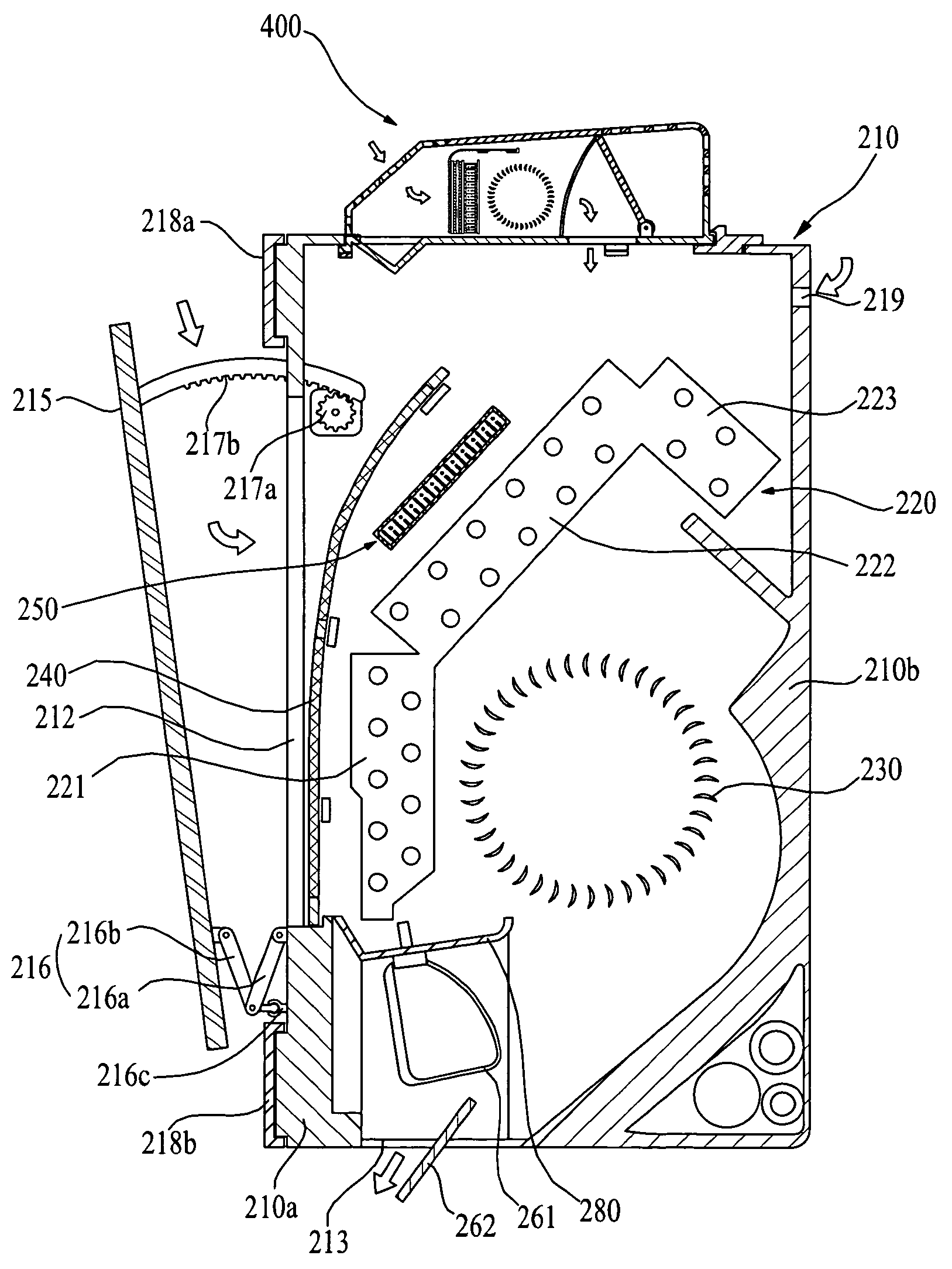
[0060]In the following, referring to the appended drawings, a wall mounted indoor unit 200 among the separate type air conditioner will be described as the indoor unit provided at the air conditioner in accordance with the present invention.

[0061]The indoor unit 200 includes a cabinet 210 having at least one air inlet, at least one air outlet, and a predetermined space therein, a fan 230 provided in the cabinet 210 and forcing air movement. The cabinet 210 includes a filter unit 400 enabling both to work together with the cabinet 210 and to independently work regardless of the cabinet 210.

[0062]A first air inlet 211 is formed on an upper surface of the cabinet 210 for drawing in the air from the outside of the cabinet 210, i.e., from the room, and a second air inlet 212 is formed on a front surface of the cabinet 210.

[0063]An air outlet 213 for discharging cooled or heated air is formed at a lower part of the cabinet 219. In this case, it is desirable that the air outlet 213 is form...

second embodiment

[0129]In the following, referring to FIG. 10 and FIG. 11, the filter unit provided at the air conditioner in accordance with the present invention is described.

[0130]In this case, FIG. 10 illustrates a cross sectional view showing the filter unit provided at an indoor unit of the air conditioner in accordance with the second embodiment of the present invention, and FIG. 11 illustrates a cross sectional view showing a state that the filter unit provided at the indoor unit of the air conditioner in accordance with the second embodiment of the present invention is engaged with the cabinet of the indoor unit.

[0131]In a description of the second embodiment of the filter unit provided at the indoor unit of the air conditioner in accordance with the present invention, the same number is used for the same structure in the first embodiment of the filter unit provided in the indoor unit of the air conditioner in accordance with the present invention, thereby the description of which will be o...


PUM


Abstract

Disclosed is an air conditioner having an excellent air cleaning function, the air conditioner including a cabinet having a first air inlet and discharging conditioned air; and a filter unit provided at the cabinet and cleaning air drawn therein, and selectively performing an interlocking operation for supplying purified air to the cabinet or an independent operation for discharging the purified air directly to the outside thereof.

Description

CROSS-REFERENCE TO RELATED APPLICATIONS[0001]This application claims the benefit of Korean Application No. P2004-64424, filed on Aug. 16, 2004, which is hereby incorporated by reference as if fully set forth herein.BACKGROUND OF THE INVENTION[0002]1. Field of the Invention[0003]The present invention relates to an air conditioner, and more particularly, to an air conditioner having an indoor unit provided in a room for cooing and heating a room.[0004]2. Discussion of the Related Art[0005]In general, an air conditioner is an apparatus for controlling temperature and humidity of air in a particular area according to a use. As an example of the air conditioner, there is an apparatus having a compressor and a heat exchanger for flowing refrigerant to cool or heat such an indoor space as a housing space, a dining room, a library, or an office.[0006]Generally, the air conditioner is divided into an integrated type air conditioner and a separate type air conditioner. The integrated type air...

Claims


Application Information

Patent Timeline
Patent Type & Authority Patents(United States)
IPC IPC(8): F25D17/04F24F1/0073F24F1/0057F24F1/0063F24F1/0067F24F8/108F24F8/158F24F8/167
CPCF24F1/0007F24F3/1603F24F13/20F24F2001/0048F24F2003/1625F24F2003/1628F24F2003/1682F24F1/0057F24F8/167F24F8/158F24F8/30F24F1/0067F24F1/0073F24F1/0063F24F8/108F24F13/28F24F1/00B82Y40/00
Inventor KANG, DONG HOON
Owner LG ELECTRONICS INC
Why Eureka
Try Eureka