Air circulator

a technology of air circulator and air circulation range, which is applied in the direction of machines/engines, liquid fuel engines, separation processes, etc., can solve the problems of difficult to build into existing buildings, difficult to achieve the construction of conventional central ventilation systems, and relatively high cost, so as to improve air mobility and fluidity, improve air purification effect, and increase the effect of circulation rang

Active Publication Date: 2021-02-16
AIRPPLE ELECTRONICS TECH XIAMEN
View PDF30 Cites 3 Cited by
  • Summary
  • Abstract
  • Description
  • Claims
  • Application Information

AI Technical Summary

Benefits of technology

[0010]Another advantage of the invention is to provide an air circulator, wherein the flowing air is guided to turn and flow through a flowing path from bottom to top, wherein the flowing path has a turning corner with a predetermined turning angle to improve the air mobility and fluidity by changing the flowing direction of flowing air.
[0011]Another advantage of the invention is to provide an air circulator which collects outside air at a lower portion thereof and discharges the air upwardly in a spiral manner, wherein the inletting air from the bottom is sucked and driven to flow upwardly and spirally for a farer distance to increase the circulation range thereof.
[0012]Another advantage of the invention is to provide an air circulator providing better air purifying effect by enabling the inletting air to be deposited at the turning corner and, in addition, providing a filter element at the turning corner for high-efficient filtering.
[0013]Another advantage of the invention is to provide an air circulator that purifies inletting air at the lower portion and upwardly sucks and delivers the purified air to discharge so as to reduce the possibility of repeatedly purifying the purified air and thus enhance the air purification efficiency of the environment.
[0014]Another advantage of the invention is to provide an air circulator, wherein the inletting air is purified and delivered upwards to discharge purified air up to a position with a predetermined height to meet the actual living need of people without the need to elevate the placing height of the air circulator.
[0015]Another advantage of the invention is to provide an air circulator comprising at least a filter unit which can be detached from a lower portion thereof by directly removal operation without lateral movement or shaking, so as to avoid adverse effect to the surrounding environment and reduce the possibility of secondary air pollution while replacing the filter unit.

Problems solved by technology

However, conventional air circulation devices have some disadvantages.
For example, conventional central ventilation system is difficult to build into an existing building because substantial modification is required to structure of the building and the cost thereof is relatively high.
In addition, most of the old buildings are not suitable for remodeling.
For another example, the conventional air purifier or circulation fan is in a larger overall size, especially the conventional air purifier with high purification efficiency, which not only has high complexity in purifying mechanism, but also increases the maintenance cost of the multi-layer filter.
However, many conventional air circulation devices are designed to merely provide one of the two functions, either filtration or circulation.
Furthermore, in order to enhance the purification efficiency of the conventional air purifier, one of the improvement methods is to enhance and complicate the filtration process, but it directly reduces the air mobility.
Conventional air purifier has a linear filtration path with one way direction to filtrate the air flowing therethrough, wherein although the linear flowing path increases the purification efficiency via the complicated filtration procedures, the filtration range and area is limited that only a specific and limited range of air is filtered repeatedly.
In other words, it fails to increase the air mobility while the cost of the equipment is increased.
When the filtering range of indoor space is limited by the air circulation, it is meaningless to the decontaminate work of a room while it merely filter a limited region in that room.
Another disadvantage is that the conventional air circulation device is generally designed with high power in order to achieve circulation coverage in a large area region.
If the indoor space is relatively large, the mobility in the entire space is difficult to be covered with a single air filter device, and it is also harder to filter the entire space merely relying on a single air filter device.
The conventional air circulation device looks pretty bulky and is a source of noise and vibration at home.
Also, due to the larger space to be occupied by the convention air circulation device, it is not easy to reduce costs and difficult to enhance its mobility and flexibility.
The conventional air circulation device contains parts and components for controlling the air flow which are heavy and large in size that causes much inconvenience to the device.

Method used


Image

  • Air circulator
  • Air circulator
  • Air circulator

Examples


Embodiment Construction

[0043]The following description is disclosed to enable any person skilled in the art to make and use the present invention. Preferred embodiments are provided in the following description only as examples and modifications will be apparent to one skilled in the art. The general principles defined in the following description would be applied to other embodiments, alternatives, modifications, equivalents, and applications without departing from the spirit and scope of the present invention.

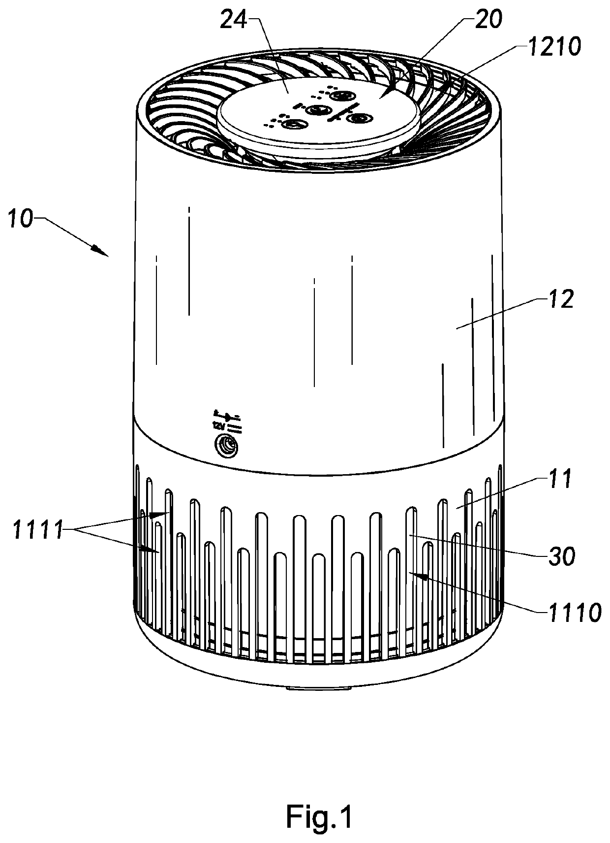
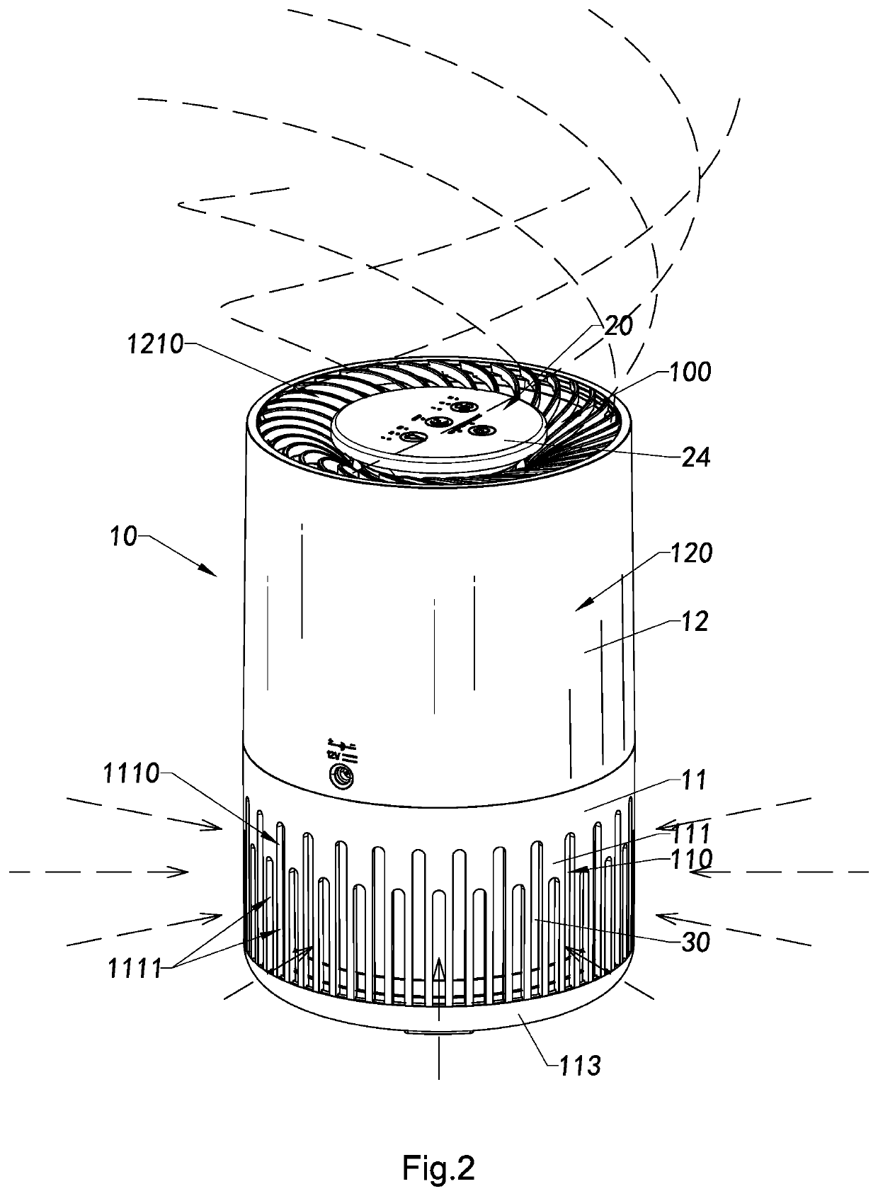
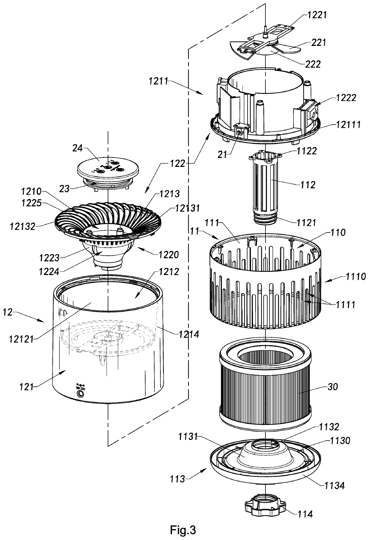
[0044]Referring to FIGS. 1 to 6 of the drawings, the present invention provides an air circulator, which comprises an airflow guiding housing 10 and a power assembly 20 installed in the airflow guiding housing 10. The airflow guiding housing 10 has an air inlet 1110 formed at a lower peripheral side thereof, an air outlet 1210 formed at a top side thereof and an airflow channel 100 extending from the air inlet 1110 to the air outlet 1210 in the airflow guiding housing 10. The power assembly 20 comp...


PUM

PropertyMeasurementUnit
sizeaaaaaaaaaa
timeaaaaaaaaaa
structureaaaaaaaaaa

Abstract

An air circulator includes an airflow guiding housing and a power assembly. The power assembly is disposed in said airflow guiding housing which sequentially has a purifying chamber and a guiding chamber from bottom to top. The power assembly is operated to drive air to flow into the purifying chamber through an air inlet formed on a bottom peripheral side of the airflow guiding housing radially and deliver along an airflow channel inside the airflow guiding housing. The airflow channel further has an airflow turning portion in the purifying chamber to drive the air in the purifying chamber to turn from a radial direction to and an upward direction to flow into the guiding chamber and discharge out through an air outlet formed on top of the airflow guiding channel upwardly, outwardly and helically.

Description

NOTICE OF COPYRIGHT[0001]A portion of the disclosure of this patent document contains material which is subject to copyright protection. The copyright owner has no objection to any reproduction by anyone of the patent disclosure, as it appears in the United States Patent and Trademark Office patent files or records, but otherwise reserves all copyright rights whatsoever.BACKGROUND OF THE PRESENT INVENTIONField of Invention[0002]The present invention relates to electrical appliance, and more particular to an air circulation and guiding device for promoting and facilitating air flow within a predetermined airspace.Description of Related Arts[0003]Interior space is a relatively closed space that the air within the interior space may not have the same flowing and smooth feeling as the outdoor air circulation. With the further understanding of air pollution and the need of respiratory health, great attention is paid to the indoor air circulation system. Many buildings are now equipped wi...

Claims


Application Information

Patent Timeline
Patent Type & Authority Patents(United States)
IPC IPC(8): B01D46/00F04D29/70F04D29/32F04D29/22F04D29/44B01D46/24
CPCF04D29/703B01D46/0005B01D46/0045B01D46/0047B01D46/24F04D29/2238F04D29/325F04D29/444F04D19/002F04D25/08F04D29/542F05D2250/52
Inventor XIAO, YONGRUI
Owner AIRPPLE ELECTRONICS TECH XIAMEN
Why Eureka
Try Eureka