Plural output switching regulator with phase comparison and delay means

a phase comparison and delay technology, applied in the direction of electric variable regulation, process and machine control, instruments, etc., can solve the problems of increased audible noise due to the difference between the switching frequencies, etc., to prevent the rise of the ripple voltage of the input power source and prevent audible noise from occurring

Inactive Publication Date: 2007-09-11
MONTEREY RES LLC
View PDF3 Cites 16 Cited by
  • Summary
  • Abstract
  • Description
  • Claims
  • Application Information

AI Technical Summary

Benefits of technology

[0008]The present invention has been made for the purpose of solving at least one of the problems involved in the above-described background art and has an object to provide a DC-DC converter control circuit and a DC-DC converter control method, each of which enables preventing the occurrence of audible noise due to the differences between the switching frequencies, as well as preventing the increase in the input power source ripple voltage due to the simultaneous on / off operations of the main switching transistors.
[0015]As a result of the above-described operation, the feedback control for adjusting the period of the detection signal is performed according to the phase difference between the detection signal and the phase reference signal. As a result of this, it is possible to cause a coincidence of the period of the phase reference signal with the period of the detection signal and, in addition, to obtain an amount of retardation time that makes the phase difference between the phase reference signal and the detection signal zero.
[0016]As a result of this, it becomes possible to control so that the oscillation frequency of the DC-DC converter may coincide with the frequency of the phase reference signal. Accordingly, it becomes possible to prevent audible noise from occurring due to the difference between the frequency of the phase reference signal and the oscillation frequency of the DC-DC converter. Also, by suitably setting the frequency of the phase reference signal, it becomes possible to control the oscillation frequency of the DC-DC converter to a prescribed value of frequency.
[0017]Also, as a result of this, it becomes possible to achieve a synchronization of the detection signal and the phase reference signal. Accordingly, for example, in a case where performing switching control of separate DC-DC converters through the use of the phase reference signal and the detection signal, since it is possible to prevent the occurrence of the simultaneous “on” / “off” operations of the main switching transistors, it is possible to prevent the increase in the input power source ripple voltage.

Problems solved by technology

Accordingly, there is a possibility that when operating a plurality of DC-DC converters, owing to the difference between the operating frequencies, audible noise will occur due to the difference between the switching frequencies.
Therefore, this technique involves a problem.
Also, when the operating frequency fluctuates with the result that the simultaneous on / off operations of the main switching transistors happen, the ripple voltage of the input power source increases.
This also causes a problem.
These problems are phenomena that are unpreferable to the system.

Method used


Image

  • Plural output switching regulator with phase comparison and delay means
  • Plural output switching regulator with phase comparison and delay means
  • Plural output switching regulator with phase comparison and delay means

Examples


Embodiment Construction

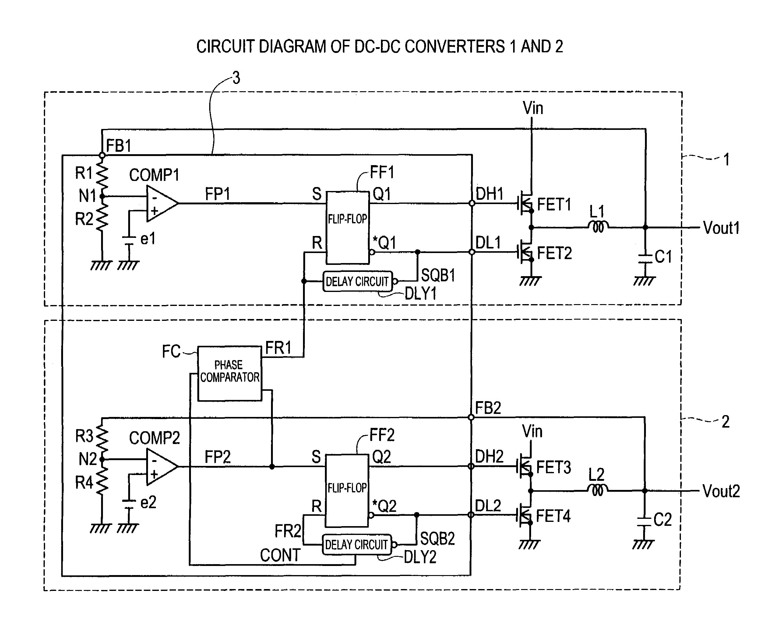
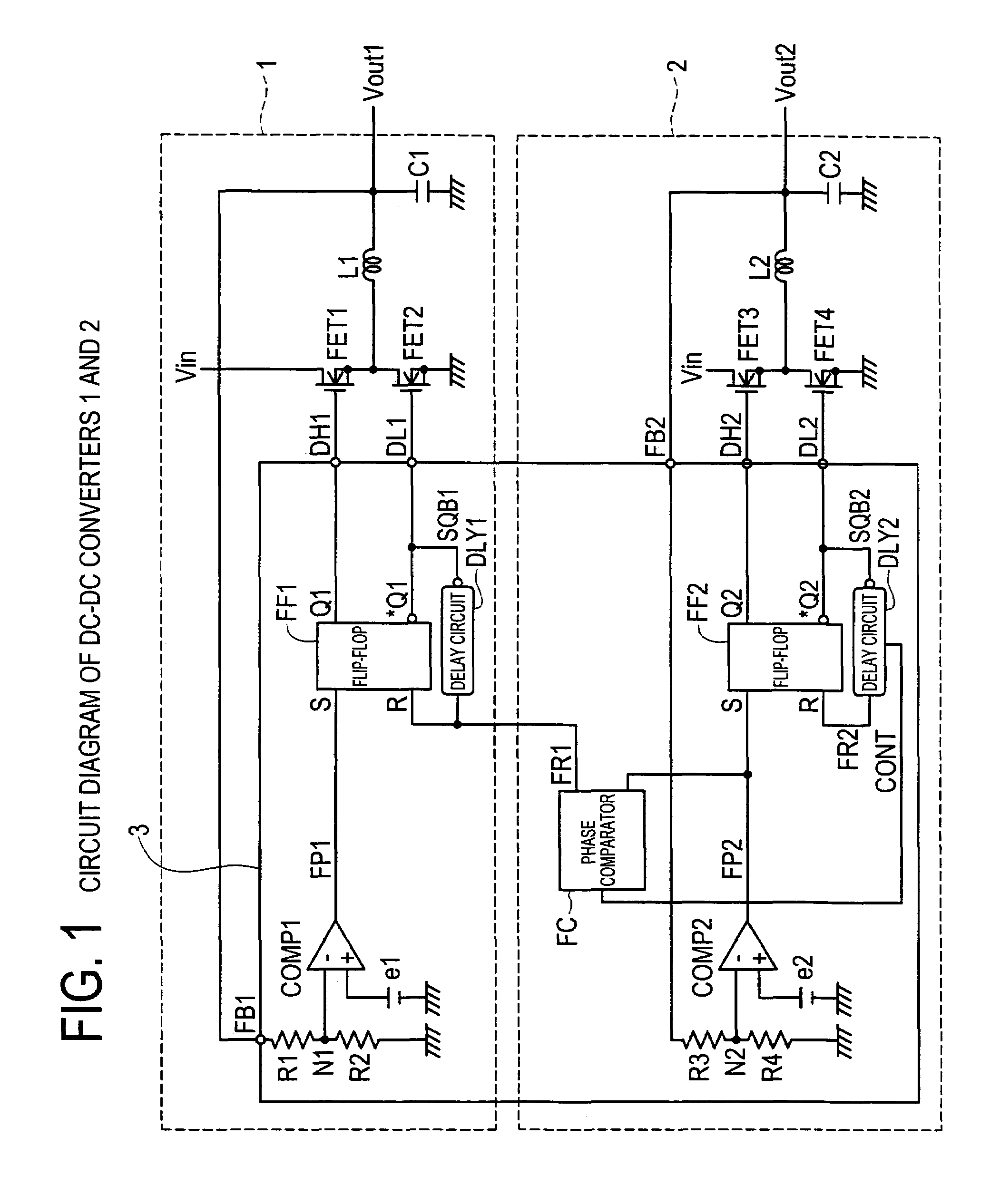
[0028]FIG. 1 is a circuit diagram of comparator type DC-DC converters 1 and 2 according to the present invention. The DC-DC converters 1 and 2 have a control part 3 that is common to each converter. First, the construction of the DC-DC converter 1 will be explained. In FIG. 1, to an input terminal of a transistor FET 1 that is a switching element, there is connected an input voltage Vin, and, to an output terminal of the transistor FET 1, there is connected an input terminal of a choke coil L1. From an output terminal of the choke coil L1, there is output an output voltage Vout1. Also, to a control terminal of the transistor FET1, there is connected an output terminal DH1 of the control part 3. An input terminal of a transistor FET2 which is a synchronous commutation switch circuit is earthed, and an output terminal thereof is connected to the input terminal of the choke coil L1. Also, to the control terminal of the transistor FET2 there is connected an output terminal DL1 of the co...


PUM


Abstract

Disclosed are a control circuit and control method for a comparator-controlled type DC-DC converter that can prevent the generation of audible noise due to the difference between relevant switching frequencies and prevent the increase in the input power source ripple voltage. A phase comparator FC outputs a compared-result signal CONT in correspondence with the phase difference between an output signal FP2 and a delay signal FR1. A delay circuit DLY2 performs a feedback control for adjusting the amount of retardation time in correspondence with the compared-result signal CONT. And, the delay circuit DLY2 outputs a delay signal FR2 after the passage of a prescribed amount of retardation time from the time when the falling edge of an output signal SQB2 has been input. At a time t16 that is after the passage of a prescribed amount of time, there is obtained a time delay DT2b that causes the period TT1 of the delay signal FR1 and the period TT2b of the output signal FP2 to coincide with each other and that makes zero the phase difference between the delay signal FR1 and the output signal FP2.

Description

CROSS-REFERENCE TO RELATED APPLICATIONS[0001]This application is based upon and claims the benefit of priority from each of the prior Japanese Patent Application No. 2005-367132 filed on Dec. 20, 2005, the entire contents of which are incorporated herein by reference.BACKGROUND OF THE INVENTION[0002]1. Field of the Invention[0003]The present invention relates to a control circuit and control method for comparator-controlled type DC-DC converters and, more particularly, to a switching control method of the main switching transistors and a control method of operating frequencies.[0004]2. Description of the Related Art[0005]There is a comparator-controlled PFM type DC-DC converter, in which, as a control system capable of making a high-speed response to a rapid change in the level of load, the output voltage of the DC-DC converter is compared with a reference voltage to thereby make on / off control of the main switching transistors.[0006]Incidentally, as the above-described related art,...

Claims


Application Information

Patent Timeline
Patent Type & Authority Patents(United States)
IPC IPC(8): H02J1/00
CPCH02M3/158H02M2001/008H02M1/008
Inventor HASEGAWA, MORIHITO
Owner MONTEREY RES LLC
Why Eureka
Try Eureka