Auxiliary dust collection system

Active Publication Date: 2007-10-16
WITTER ROBERT M
View PDF11 Cites 101 Cited by
  • Summary
  • Abstract
  • Description
  • Claims
  • Application Information

AI Technical Summary

Benefits of technology

[0009]It is a more specific object to provide a dust collection arrangement that can be used in line between the dust producing tool and a suction source, such as a shop vacuum cleaner, that can separate out between 95% and 99% of the dust

Problems solved by technology

In practice, no one has attempted to use a true cyclonic separator as an intermediate dust separation and collection device between the dust producing tool and the shop vacuum or other source of suction that accepts the dust and air stream from the tool.
This arrangement

Method used


Image

  • Auxiliary dust collection system
  • Auxiliary dust collection system
  • Auxiliary dust collection system

Examples


Embodiment Construction

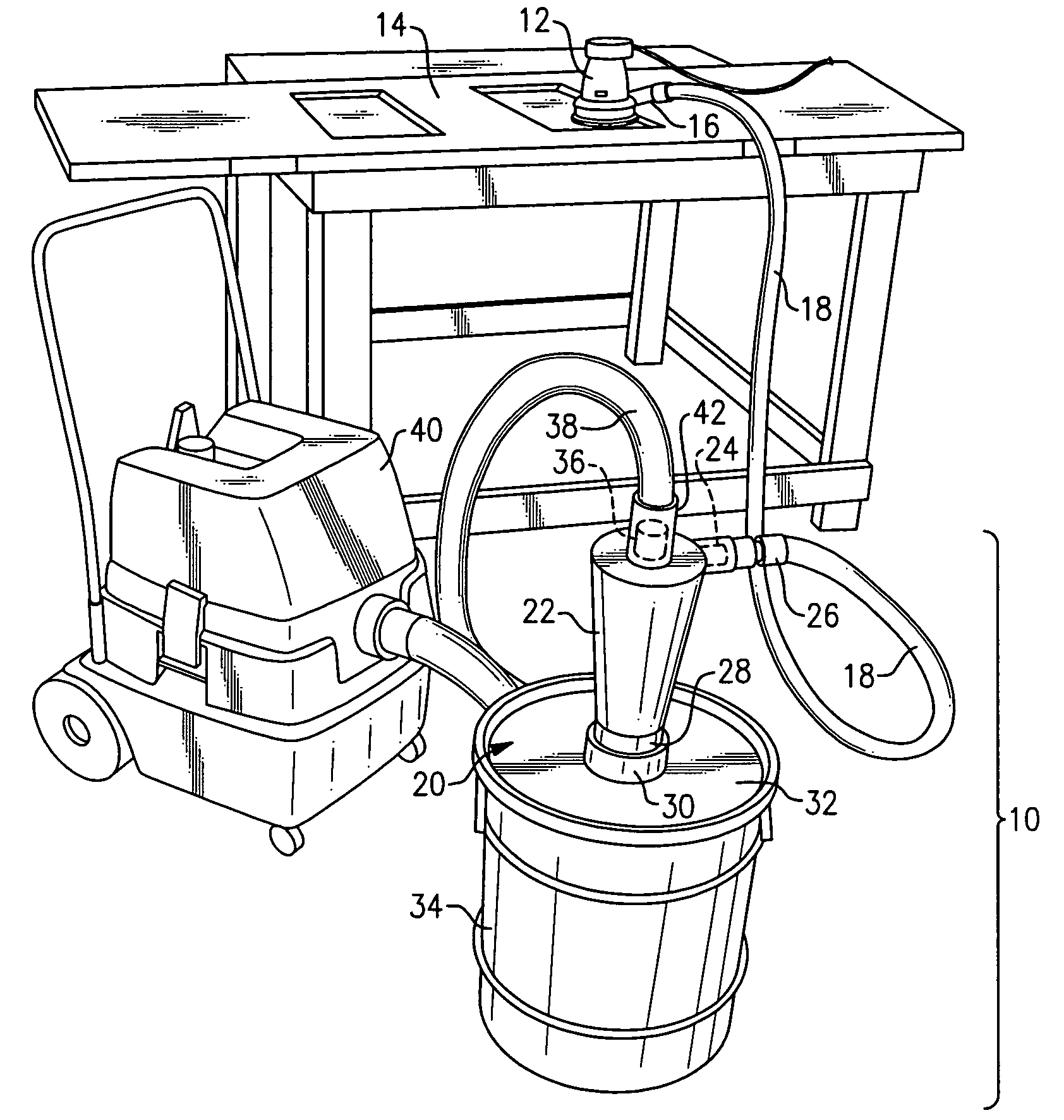
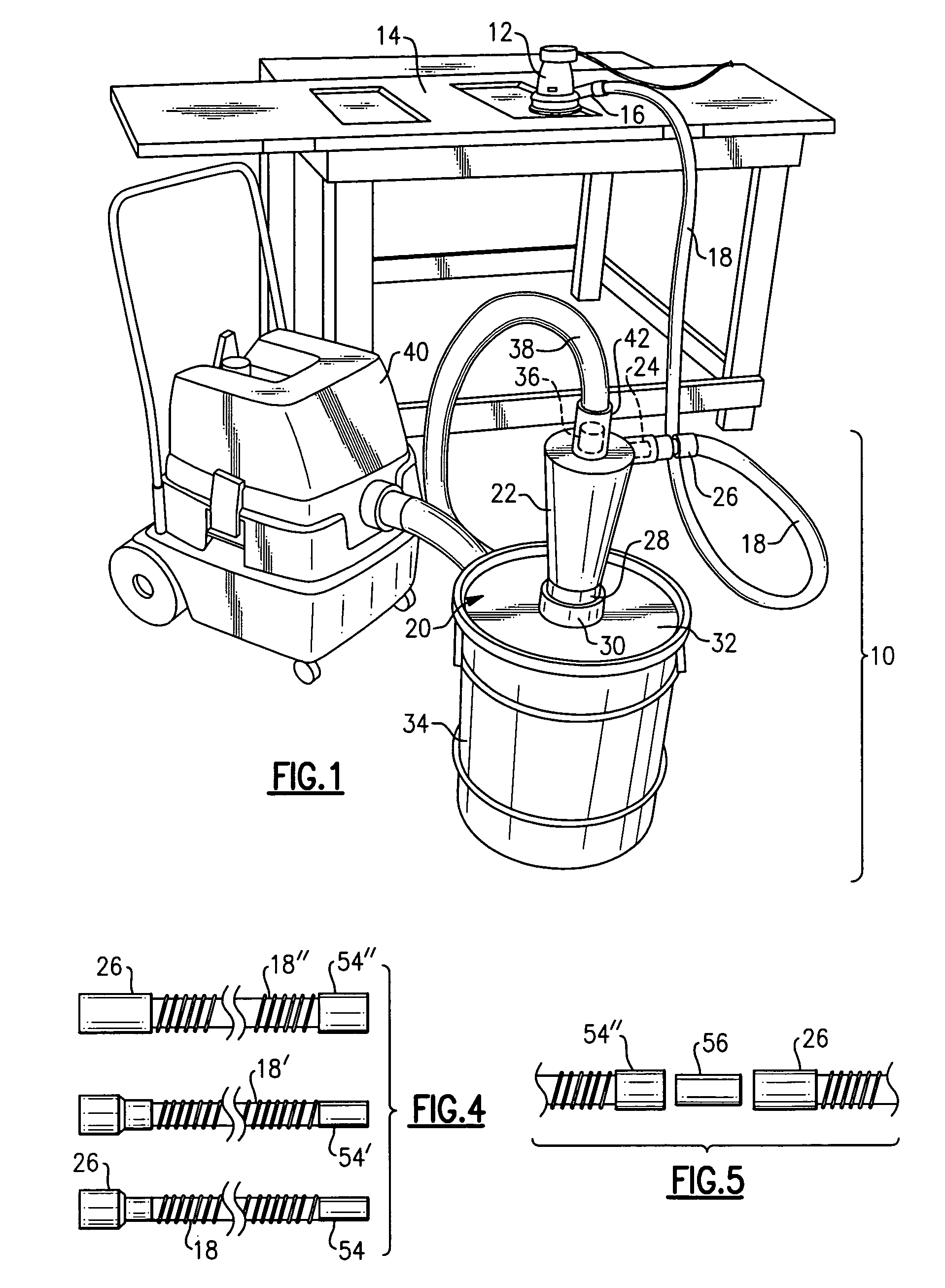
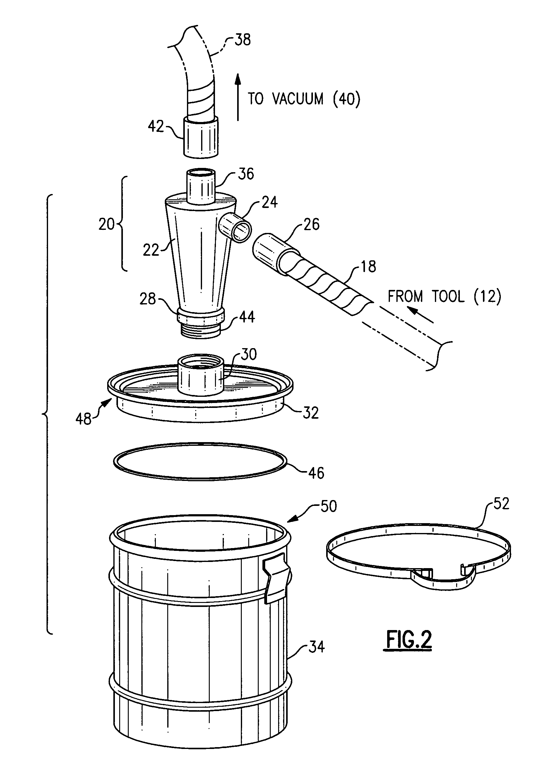
[0031]Now with reference to the Drawing, FIG. 1 shows a woodshop application, which employs an auxiliary dust separation and collection device 10 of present invention. As illustrated, a wood sander device 12 is shown in use on a wood workpiece, e.g., a door 14 or article of furniture. The sander 12 has a dust exhaust duct 16, which is connected by an elongated flexible hose 18 to an intake of the auxiliary separation and collection device. Dust in the air stream emanating from the sander 12 (or from another tool or machine) is intercepted at the auxiliary device 10, in a cyclonic separator 20. This separator comprises a conic body 22, with an intake pipe 24 that is fitted with a connector or cuff 26 of the hose 18. The cuff is favorably a tubular push-on sleeve. The conic body has a nose or vertex 28 at its lower end where it is attached by means of a coupler ring 30 to a lid or cover 32 that is fitted onto a drum or barrel 34. A vortex pipe 36 extends up from within the conic body ...


PUM

PropertyMeasurementUnit
Diameteraaaaaaaaaa
Fractionaaaaaaaaaa
Flexibilityaaaaaaaaaa

Abstract

An auxiliary dust collection system can be interposed between a sander or other dust producing tool and a vacuum source, e.g., shop vacuum. This auxiliary system has a cyclonic separator connected by a flexible hose to the tool and by another hose to the vacuum source. The cone of the separator is mounted onto the lid of a drum into which the dust precipitates. For a tool that has its own blower, the vacuum source can be omitted, and the air leaving the outlet duct of the separator can be filtered and returned to the ambient. A drop in silencer formed of a sleeve or tube of acoustic foam can be positioned into the inlet side of a filter cartridge following a cyclonic separator. The silencer absorbs a significant fraction of the process noise.

Description

BACKGROUND OF THE INVENTION[0001]This invention is directed to devices and equipment for collecting bulk solids, for example, process dust coming from a dust generating tool, such as a sanding machine, where the dust is entrained in a flow of air from the source machine, and is separated out at the dust collection equipment where the dust precipitates into a drum, barrel, or similar container. The invention is more specifically directed to a compact and efficient device to be used between a tool and a vacuum source, e.g., shop vacuum, to separate and collect the dust from the airstream emerging from the tool before the air stream reaches the vacuum source. The invention is likewise concerned with a simple and straightforward dust separation assembly that can be associated with a tool that has a duct from with the air stream plus entrained dust particles proceed.[0002]The invention is also concerned with a simple and straightforward silencer device that can be dropped in to the cylin...

Claims


Application Information

Patent Timeline
IPC IPC(8): B01D45/12
CPCB01D45/12B01D50/002B04C5/185B08B15/04B24B55/06Y10S55/18B04C2009/002B01D50/20
Inventor WITTER, ROBERT M.
Owner WITTER ROBERT M
Why Eureka
Try Eureka