Energy weapon protection device

a technology of energy weapons and protection devices, applied in the direction of shields, fire extinguishers, other domestic objects, etc., can solve the problems of inability to protect energy-type weapons such as tasers, “stun guns” or other electrical pulse-based assault devices, inability to properly operate tasers or stun guns, etc., to prevent even collateral damage to the wearer, prevent the effect of weight loss

Inactive Publication Date: 2007-10-23
OLIVE TREE FINANCIAL GROUP
View PDF9 Cites 13 Cited by
  • Summary
  • Abstract
  • Description
  • Claims
  • Application Information

AI Technical Summary

Benefits of technology

[0014]The present invention provides an energy weapon protection device to be worn by a live potential target which includes a generally flexible main panel having three main elements. The first element is a generally flexible, generally planar electrically non-conductive outer insulator panel, the second main element is a generally flexible, generally planar electrically conductive inner conductive panel and the third main element is a generally flexible, generally planar electrically non-conductive insulating backing panel. The inner conductive panel is mounted on the insulating back panel in generally parallel alignment and the outer insulator panel is mounted on the inner conductive panel in generally parallel alignment thereby forming the main panel, and the main panel is operative to receive an electrical pulse from an energy weapon through the outer insulator panel into the inner conductive panel with the inner conductive panel completing the electric circuit for the energy weapon and the insulating backing panel generally preventing electric current from passing therethrough from the inner conductive panel such that the live potential target is protected from the electrical pulse generated by the energy weapon.
[0015]The energy weapon protection device as thus described provides numerous improvements over many protection devices found in the prior art. For example, the energy weapon protection device is extremely light weight, very flexible, and may be quickly and easily added to many different types of ballistic weapon protection garments such as bullet-proof vests and body armors. Furthermore, the energy weapon protection device of the present invention is effective for use against both penetrating and non-penetrating energy weapons, and thus the user of the present invention may not be as concerned with the specific nature of the energy weapon he or she is facing, as they can be confident that either type of energy weapon will be negated by use of the present invention. Finally, because the energy weapon protection device of the present invention generally does not permit the electrode contacts of the energy weapon to get close to the skin of the target, the present invention prevents even collateral damage to the wearer, which can be invaluable in permitting a law enforcement officer to continue his or her job even when attacked. It is therefore seen that the present invention provides a substantial improvement over those devices found in the prior art.

Problems solved by technology

While such protective devices are well-suited for protection against penetration of projectile-type objects such as bullets and the like, such protective devices do not provide protection against energy-type weapons such as TASERS, “stun guns” or other electrical pulse-based assault devices.
With a non-penetrating energy weapon such as a stun gun, on the other hand, spaced-apart positive and negative electrodes protrude from the body of the stun gun and, when these are brought into contact with the skin or clothing of the target, the circuit is completed between the positive and negative electrodes and the target again is electrocuted, thus incapacitating the target.
In either case, however, proper functioning of the TASER or stun gun will incapacitate the target.
While this result is certainly acceptable when the TASER or stun gun is being used by a law enforcement officer to incapacitate a criminal in the performance of his or her duties, it is a much more serious situation when the criminal has access to the TASER or stun gun and is attempting to use it against the law enforcement officer.
As many of the TASERS and stun guns currently being marketed are available to the purchasing public, this has become a very real and very dangerous probability faced by law enforcement officers.

Method used


Image

  • Energy weapon protection device
  • Energy weapon protection device
  • Energy weapon protection device

Examples


Embodiment Construction

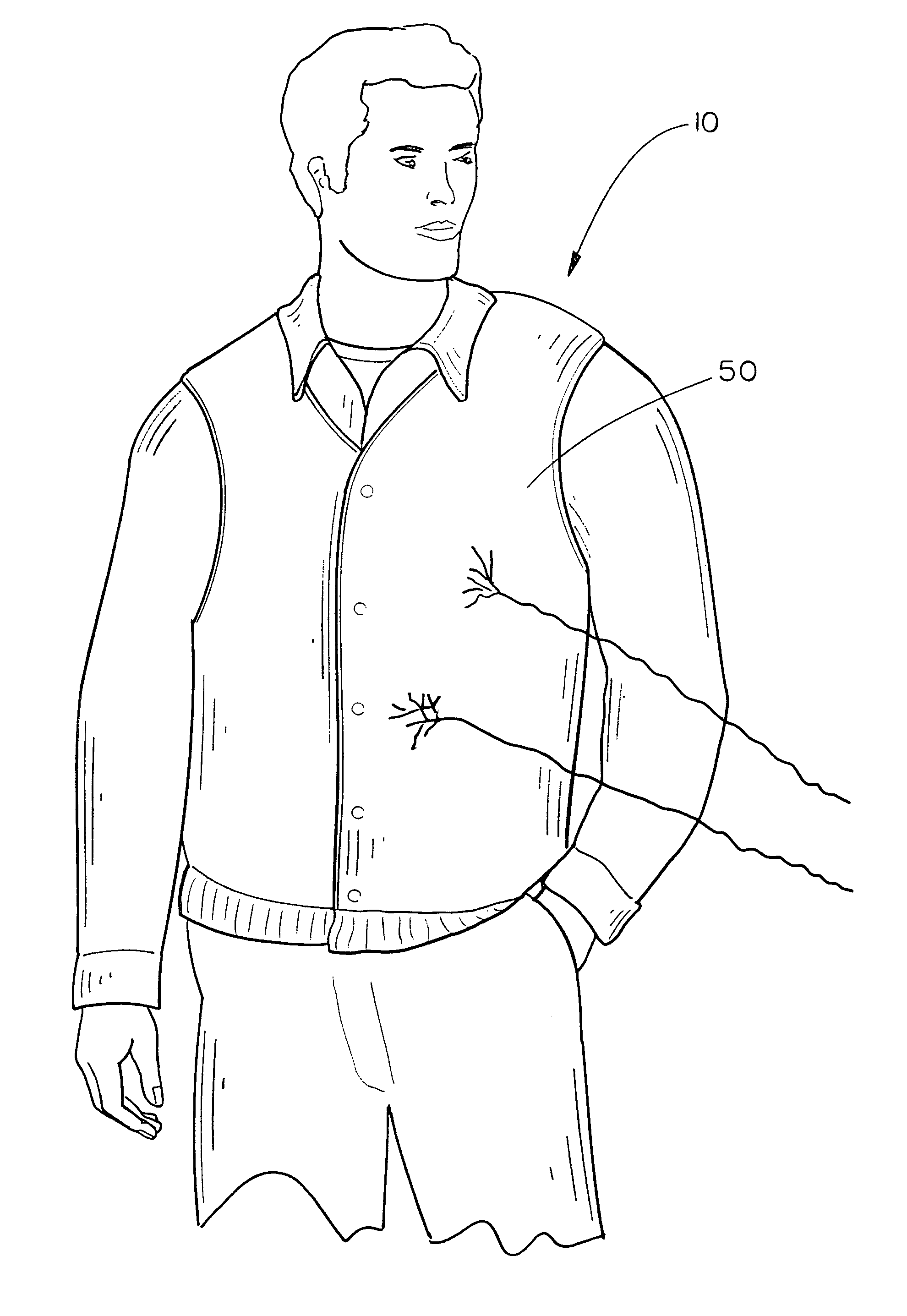
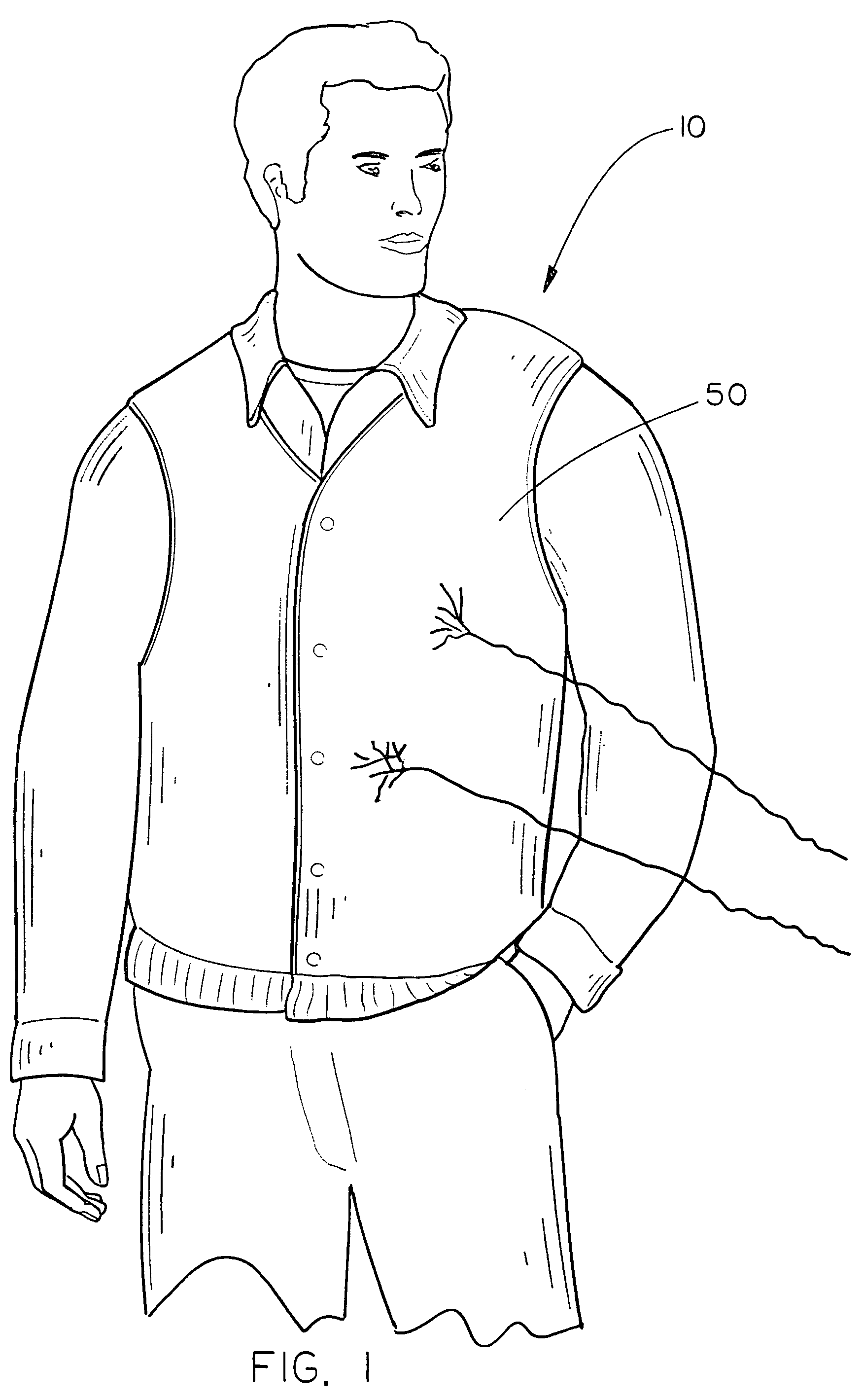
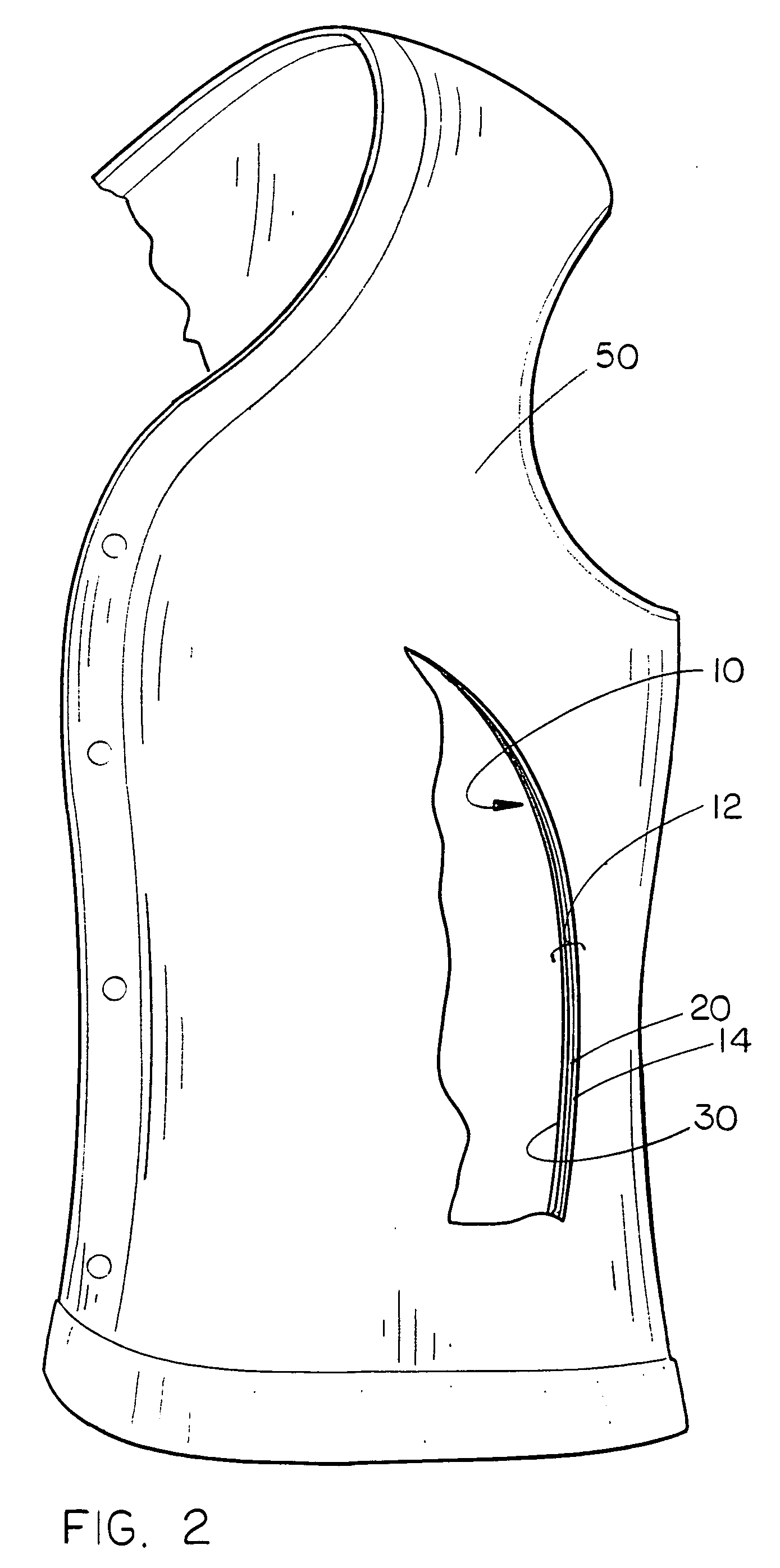
[0019]The energy weapon protection device 10 of the present invention is shown best in FIGS. 1–4 as including a three-ply main panel 12 which includes three separate material panels bonded together to form the main panel 12. The outermost panel is a non-conductive outer insulator panel 14, the middle panel is a highly electrically conductive inner conductive panel 20, and the third panel is the innermost non-conductive insulating backing material panel 30 which provides the foundation for the energy weapon protection device 10, as it is to the insulating backing panel 30 that the inner conducting panel 20 and outer insulating panel 14 are mounted. In the preferred embodiment, the outer insulating panel 14 would be constructed of a lightweight fabric material having non-conductive electrical properties and yet which would need to have a high heat tolerance due to the proximity of the electrically conductive material. Examples of appropriate fabrics would include man-made fabrics such...


PUM


Abstract

An energy weapon protection device to be worn by a live potential target includes a generally flexible main panel having three main elements, a generally flexible, generally planar electrically non-conductive outer insulator panel, an electrically conductive inner conductive panel and an electrically non-conductive insulating backing panel. The inner conductive panel is mounted on the insulating back panel in generally parallel alignment and the outer insulator panel is mounted on the inner conductive panel in generally parallel alignment thereby forming the main panel, and the main panel is operative to receive an electrical pulse from an energy weapon through the outer insulator panel into the inner conductive panel which completes the electric circuit for the energy weapon and the insulating backing panel generally preventing electric current from passing therethrough from the inner conductive panel such that the live potential target is protected from the electrical pulse generated by the energy weapon.

Description

CROSS-REFERENCE TO RELATED PROVISIONAL PATENT[0001]This application claims priority based on a provisional patent, specifically on the Provisional Patent Application Ser. No. 60 / 594,400 filed Apr. 5, 2005, which provisional patent application is incorporated by reference herein.BACKGROUND OF THE INVENTION[0002]1. Technical Field[0003]The present invention is directed to energy weapon protection devices and, more particularly, to an energy weapon protection device which is usable with many different types of vests and body armors, including bullet-proof vests and body armor, and which includes three separate layered panels, a non-conductive outer insulation panel, an electrically conductive inner conducting panel, and a non-conductive insulating backing panel, the three panels being mountable on top of the bullet-proof vest or body armor, the protection panel functioning to discharge energy weapons which are shot at a person wearing the device without permitting electrical transfer t...

Claims


Application Information

Patent Timeline
Patent Type & Authority Patents(United States)
IPC IPC(8): F41H1/00A41D27/02A62B17/00F41H5/08F41H13/00
CPCA41D13/008F41H1/02F41H13/0012Y10S2/905Y10S428/902Y10S428/911Y10S428/92
Inventor SCHULTZ, GREGORY RUSSELL
Owner OLIVE TREE FINANCIAL GROUP
Why Eureka
Try Eureka