Micro slit viscometer with monolithically integrated pressure sensors

a pressure sensor and micro-slit technology, applied in the field of miniature devices, can solve the problems of not being able to measure true viscosity with ill-defined test conditions the shear rate cannot be known or calculated, and the test conditions are not known for most non-newtonian liquids, so as to reduce the manufacturing cost of the micro-viscometer

Inactive Publication Date: 2007-11-06
RHEOSENSE
View PDF15 Cites 39 Cited by
  • Summary
  • Abstract
  • Description
  • Claims
  • Application Information

AI Technical Summary

Benefits of technology

[0006]According to the current invention, a significantly smooth interior surface of a pressure sensing area is ensured by fabricating a monolithic array of pressure sensors and combining it with separately micro-fabricated flow channels. The smooth interior surface ensures that the slit flow is less perturbed and the accurate local pressures are measured and the interior surface is less likely damaged by a deposition of test materials. The slit flow channel is constructed in a micrometer scale so that only a miniscule amount of sample is required for viscosity measurement. Additionally, the pressure sensors and flow channels are fabricated on wafers using batch microfabrication processes of Micro-Electro-Mechanical Systems. Such a batch wafer process makes many identical parts at the same time and thereby reduces manufacturing costs of the micro viscometers.
[0007]Advances in microfabrication and micromachining processes enable the miniaturization of sensitive solid-state pressure sensors. Such a reduction in size allows in turn the densification of functionalities. Also the technical advances in microfabrication makes tailoring of pressure sensor sensitivity easier along with improvements in read out circuit designs. These improvements allow the tailoring of the micro viscometers to various purposes and for measuring wide ranges of viscosity.

Problems solved by technology

But in many cases viscosity is measured under ill-defined test conditions so that shear rate can not be known or calculated.
However, a “constitutive equation” is not known for almost all Non-Newtonian liquids.
Therefore, true viscosity can not be measured with ill-defined test conditions for most non-Newtonian liquids.
However, because of the non-universality of the apparent viscosity measurement, a correlation of the apparent viscosity of a specific sample measured with a specific method to the true viscosity has to be found separately, when desired.
Therefore they are usually expensive.
Also, the rheometers are not well suited for on-line applications.
However, the use of two capillaries makes the viscometer bulky and measurements time consuming.
Any slight surface roughness due to the mounting of the pressure sensors may be a source of test sample deposition which degrades long term performance.
Mounting of individual pressure sensors to eliminate surface roughness is difficult.
Therefore, the measurement accuracy is often compromised depending on how well the individual pressure sensors are mounted in the flow channel.
Therefore, these conventional slit viscometers are not appropriate for measuring viscosities of test samples that are only available in a small quantity.

Method used


Image

  • Micro slit viscometer with monolithically integrated pressure sensors
  • Micro slit viscometer with monolithically integrated pressure sensors
  • Micro slit viscometer with monolithically integrated pressure sensors

Examples


Embodiment Construction

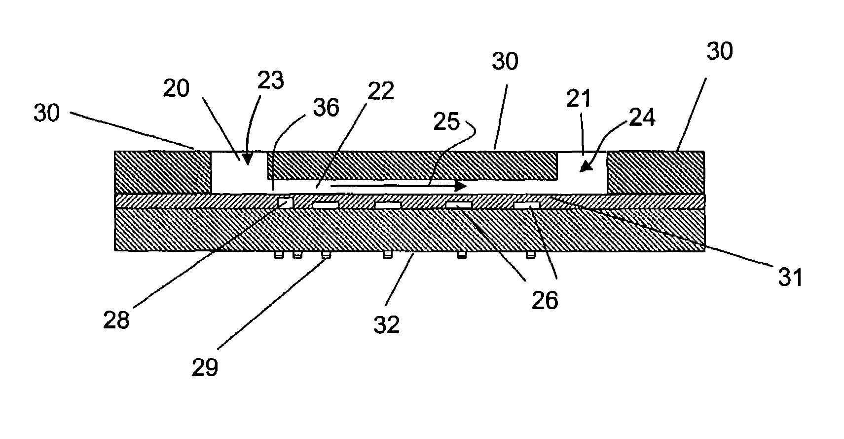
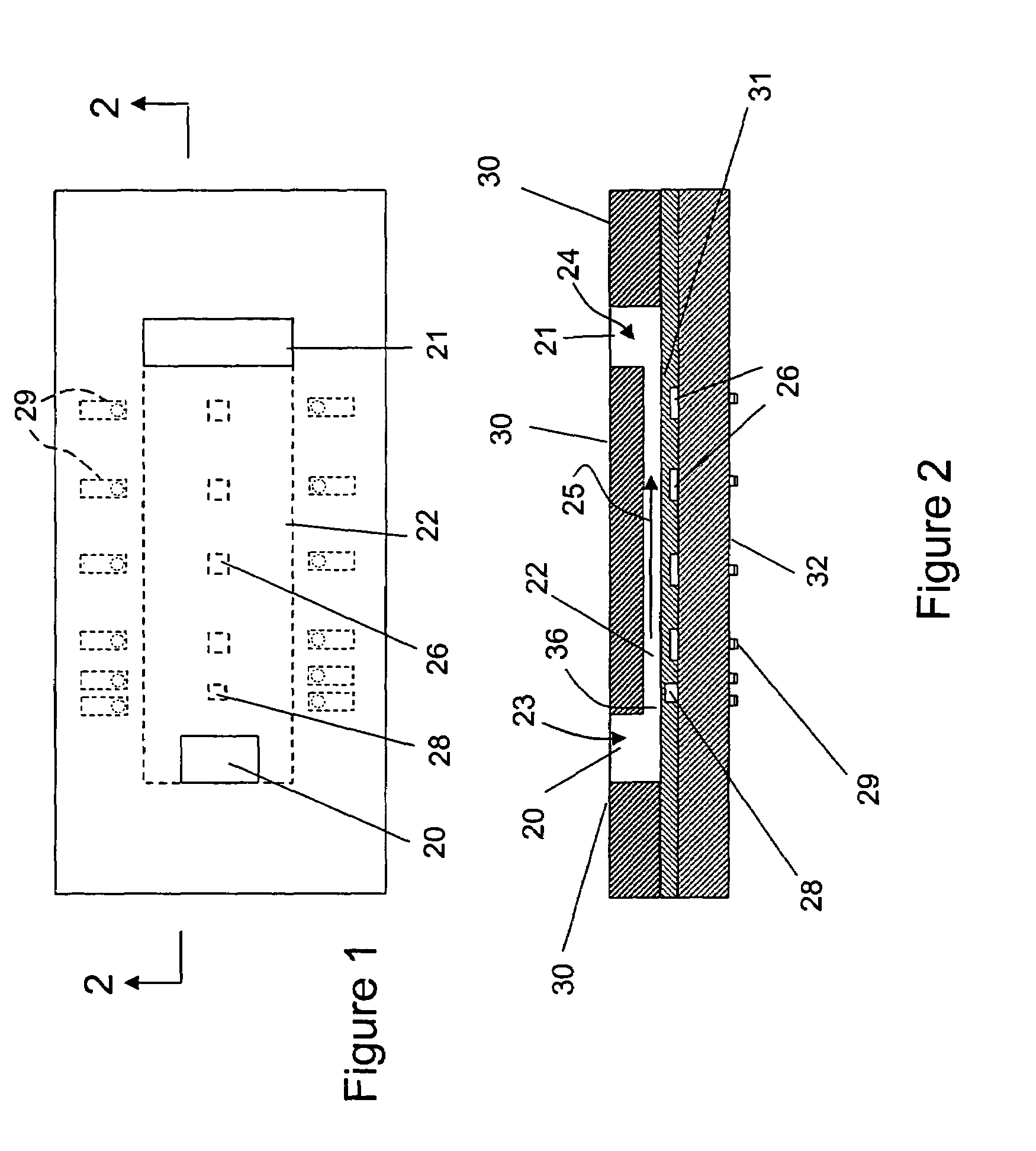
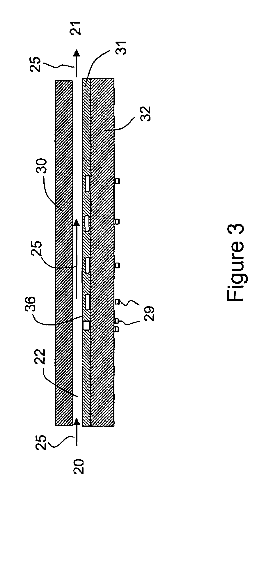
[0037]An embodiment of a micro slit flow cell of the invention is shown in FIGS. 1 and 2 and includes a flow entrance or inlet 20, a flow exit or outlet 21, and a flow channel 22 therebetween. The flow channel 22 has a predetermined uniform depth (gap) in the micrometer range along the channel. The width of the channel is significantly larger than the depth of the channel so that the flow through the channel can be considered to be a one-dimensional problem instead of a two dimensional problem. The ratio of the width to the depth is preferably larger than ten. The preferred depth of the channel is in the order of a micrometer. The preferred length of the channel is at least one hundred micrometers excluding the entrance and exit zones, 23 and 24, respectively. In order to measure the true viscosity of a test liquid, the test liquid is forced to flow through the flow channel 22 of the micro slit flow cell by a pumping system, not shown, at a controllable constant volumetric flow rate...


PUM

PropertyMeasurementUnit
widthaaaaaaaaaa
lengthaaaaaaaaaa
widthaaaaaaaaaa

Abstract

An improved micro slit viscometer includes a combined micrometer depth rectangular slit flow channel with monolithically integrated multiple pressure sensors in the flow channels and a pumping system that injects a test sample to the channel at a desired flow rate. Pressure sensing diaphragm of the monolithically integrated pressure sensors is smooth to minimize the flow disturbance thereby measuring accurate local pressures. With the measurement of the pressures at various locations of the channel the true viscosity of test sample can be calculated. The viscometer may consist of multiple flow channels and thus the true viscosity at multiple shear rates can be measured simultaneously for a given flow rate thereby obtaining a full viscosity curve as a function of shear rate of non-Newtonian liquids in a much faster manner. The viscometer needs only a miniscule amount of sample, which minimizes a waste of test material. The flow channels and the monolithically integrated pressure sensors are fabricated using microfabriaction processes on wafers and combined, which greatly reduce the production costs.

Description

RELATED APPLICATIONS[0001]This application is a continuation-in-part of U.S. patent application Ser. No. 10 / 286,602, filed Oct. 31, 2002, now U.S. Pat. No. 6,892,583, which claimed the benefit of provisional application Ser. No. 60 / 335,375, filed Oct. 31, 2001, both entitled “Pressure Sensing Device For Rheometers.” This application also claims the benefit of U.S. Provisional Patent Application Ser. No. 60 / 552,289, filed Mar. 11, 2004, and entitled “Micro Slit Viscometer with Monolithically Integrated Pressure Sensors.” All of the above applications are incorporated herein by reference.BACKGROUND OF INVENTION[0002]Field: This invention is in the field of miniature devices that measure true viscosities of liquid.[0003]State of the art: Viscosity is a measure of resistance of liquid to flow and its value depends on the rate of deformation for Non-Newtonian liquids as described in Dynamics of Polymeric Liquids, Vol. 1, 1987 authored by R. B. Bird, R. C. Armstrong, and O. Hassager. The ...

Claims


Application Information

Patent Timeline
Patent Type & Authority Patents(United States)
IPC IPC(8): G01N11/08G01N21/00
CPCG01N11/08
Inventor BAEK, SEONG-GI
Owner RHEOSENSE
Why Eureka
Try Eureka