Image forming apparatus wherein a speed of a developed carrying member is controlled relative to a speed of an image bearing member

a technology of image bearing and carrying member, which is applied in the direction of electrographic process apparatus, instruments, optics, etc., can solve the problems of low peripheral speed of the developing sleeve, and achieve the effect of suppressing fog

Active Publication Date: 2008-01-08
CANON KK
View PDF6 Cites 24 Cited by
  • Summary
  • Abstract
  • Description
  • Claims
  • Application Information

AI Technical Summary

Benefits of technology

[0026]So, the present invention has as its object to suppress the fog when in an image forming apparatus which can effect image formation at two kinds of rotating speeds of an image bearing member, the rotating speed of the image bearing member is made

Problems solved by technology

However, when at an image forming mode in which the peripheral speed of the photosensitive drum is thus made lower than that at the normal image forming mode, the peripheral speed of the developing sleeve is also made low at the same rate without the peripheral speed ratio being changed, the following problems have arisen.
However, when the peripheral speed ratio Vr is too small, even the toner having a normal charging amount does not sufficiently rise in charging rate and therefore, depending on the construction of the developing apparatus used, the developing bias, the kind of the developer, etc., it is necessary to provide an appropriate peripheral speed ratio.
In contrast, the toner having a low charging amount indicated by the area “A” in FIG. 13 is bad in its follow-up property to the developing bias and therefore, even when it is supplied to the developing nip portion, it does not immediately move to the dark portion potential (in the case of reversal development) of the photosensitive drum.

Method used


Image

  • Image forming apparatus wherein a speed of a developed carrying member is controlled relative to a speed of an image bearing member
  • Image forming apparatus wherein a speed of a developed carrying member is controlled relative to a speed of an image bearing member
  • Image forming apparatus wherein a speed of a developed carrying member is controlled relative to a speed of an image bearing member

Examples


embodiment 1

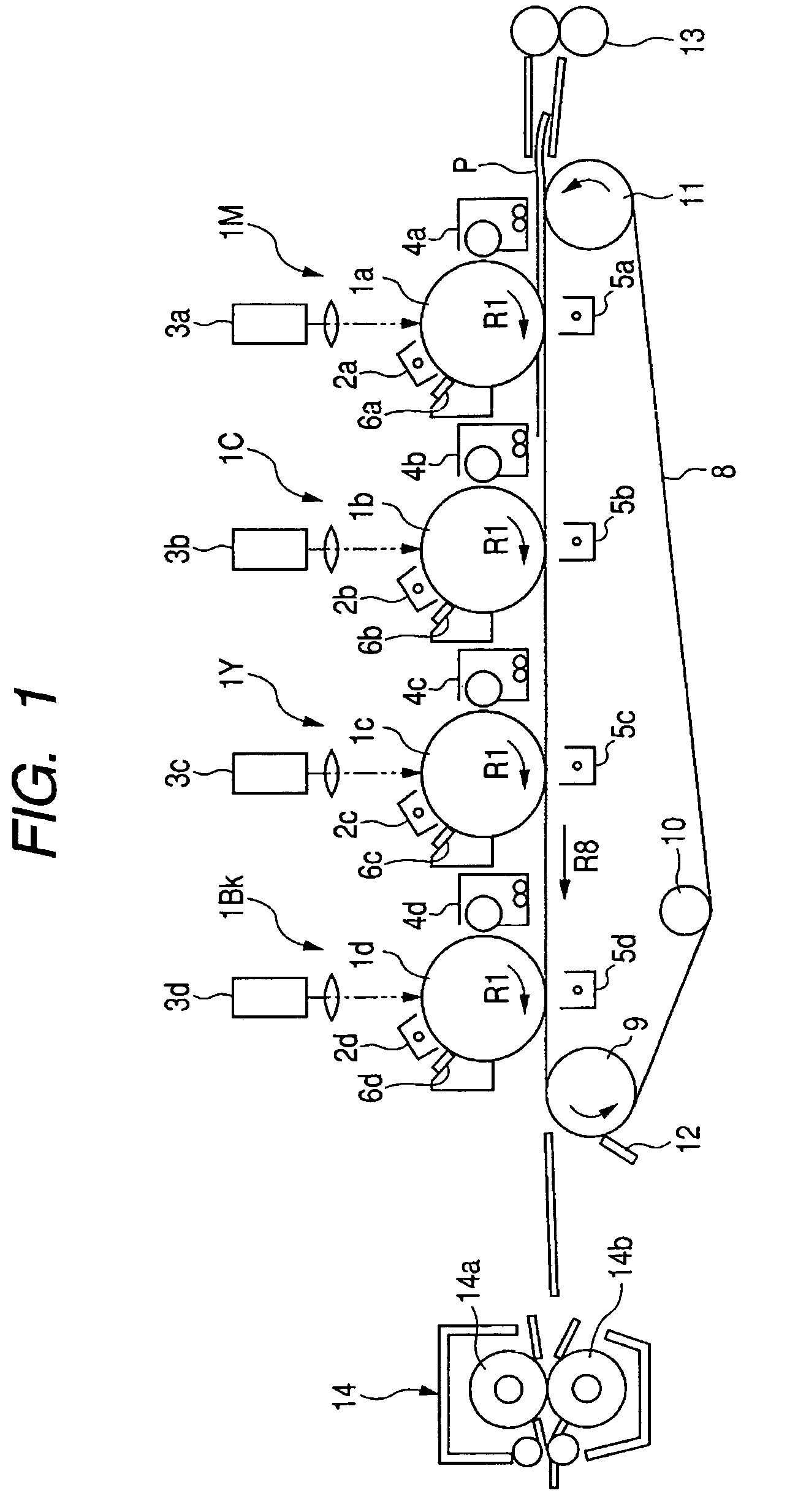
[0048]FIG. 1 shows an image forming apparatus to which the present invention can be applied. The image forming apparatus shown in FIG. 1 is a four color full-color printer having four image forming portions of an electrophotographic printing method, and FIG. 1 is a longitudinal cross-sectional view schematically showing the construction thereof.

[0049]The printer (hereinafter referred to as the “image forming apparatus”) shown in FIG. 1 has four image forming portions disposed along the movement direction (the direction indicated by the arrow R8) of a transfer belt 8, i.e., image forming portions 1M, 1C, 1Y and 1Bk for forming magenta (M), cyan (C), yellow (Y) and black (Bk) toner images, respectively, in succession from an upstream side.

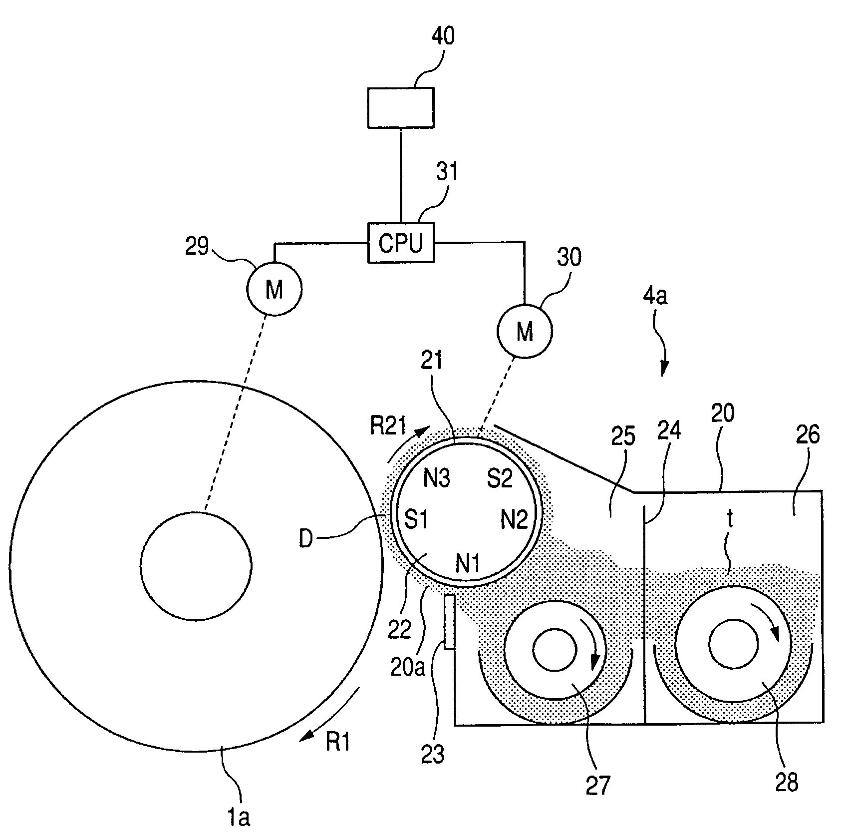
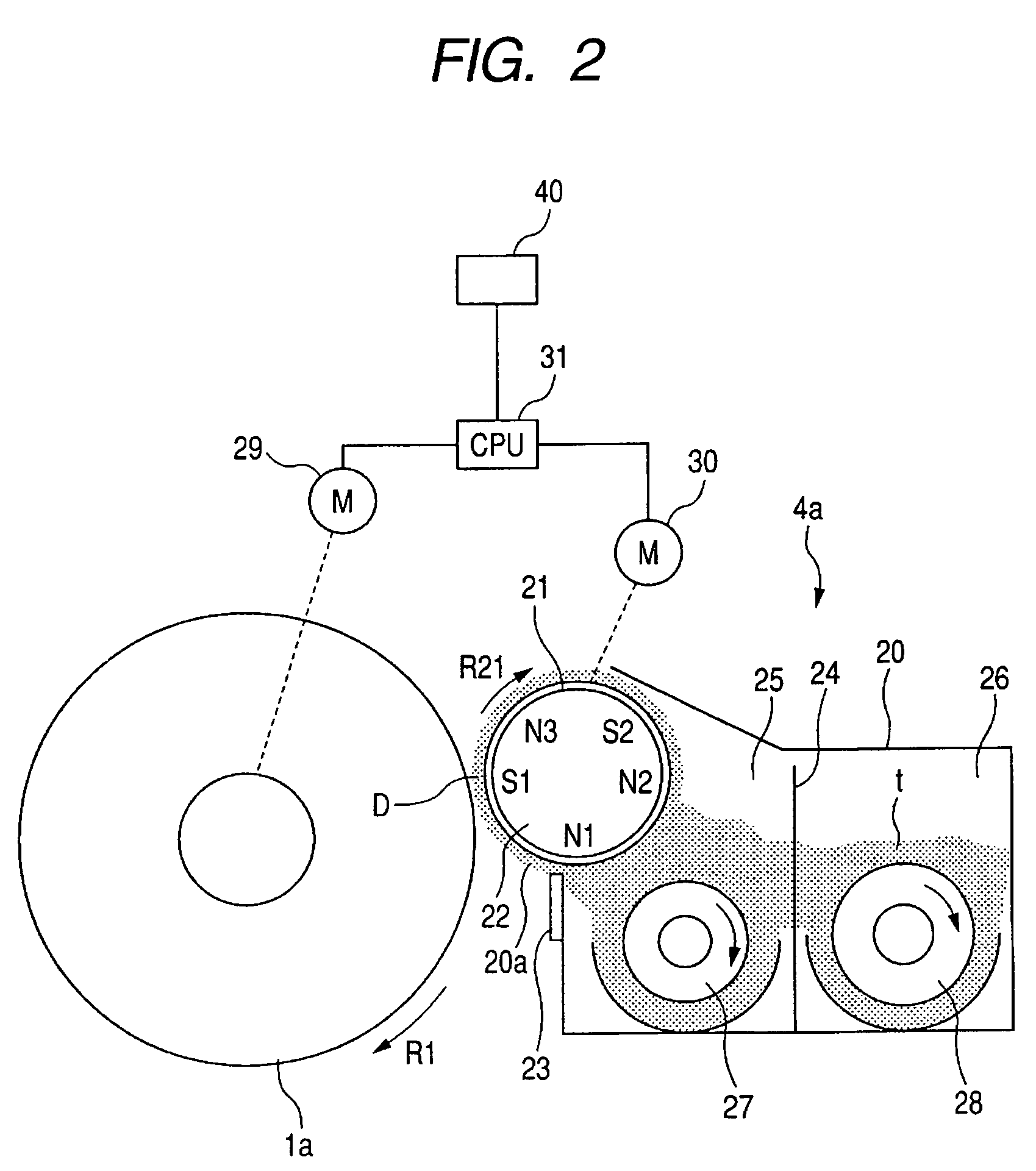
[0050]Drum-shaped electrophotographic photosensitive members (hereinafter referred to as the photosensitive drums) 1a, 1b, 1c and 1d as image bearing members are disposed in the respective image forming portions 1M, 1C, 1Y and 1Bk for rotation in the...

embodiment 2

[0081]Embodiment 2 will now be described. The general constructions of an image forming apparatus and a developing apparatus according to this embodiment are similar to those of Embodiment 1 described above, but this embodiment is characterized in that at an image forming mode whereat the peripheral speed of the photosensitive drum becomes lower than that at a normal image forming mode, the peripheral speed ratio of the developing sleeve to the photosensitive drum is made variable in accordance with the period of use of the developer.

[0082]The charging amount distribution of the toner in the developing apparatus becomes such a distribution as indicated by solid line “a8” in FIG. 8. The proportion of a toner of which the charging amount is in the vicinity of 0 (zero) or a toner charged to the opposite polarity is very low. However, when the period of use of the developer becomes long, the states of carrier particles and the developing sleeve on the side giving charges or the states o...

embodiment 3

[0092]Embodiment 3 will now be described. The general construction of an image forming apparatus according to this embodiment is similar to that of Embodiments 1 and 2, but the present embodiment is characterized in that at an image forming mode such as the OHT mode whereat the peripheral speed of the photosensitive drum is made lower than at the normal image forming mode, the ratio of the peripheral speed of the agitating means to the peripheral speed of the developing sleeve is changed.

[0093]In the developing apparatus of an image forming apparatus, the developing sleeve and the agitating means are generally connected to the driving gear of an image forming apparatus main body through one and the same gear train, and the peripheral speed ratio between the two is fixed and therefore, when the peripheral speed of the developing sleeve is made high, the peripheral speed of the agitating means also becomes high. If in such a construction, as in Embodiments 1 and 2, at the image formin...


PUM


Abstract

An image forming apparatus includes a rotatable image bearing member bearing an electrostatic image; a rotatable developer carrying member carrying a developer to develop the electrostatic image; speed controlling means for switching a rotating speed of the image bearing member between a first speed and a second speed lower than the first speed, and performing an image forming operation at each speed; and developer carrying member speed controlling means for controlling a rotating speed of the developer carrying member so that a rotating speed of the developer carrying member when the image forming operation is performed by rotating the image bearing member at the second speed, which is less than 70% of the first speed so as to be within a range of ±30% of a rotating speed of the developer carrying member when the image forming operation is performed by rotating the image bearing member at the first speed.

Description

BACKGROUND OF THE INVENTION[0001]1. Field of the Invention[0002]The invention relates to an image forming apparatus such as a printer, a copying machine or a facsimile apparatus of an electrophotographic printing method.[0003]2. Related Background Art[0004]An image forming apparatus such as a printer, a copying machine or a facsimile apparatus using an electrophotographic printing method is generally provided with a photosensitive drum as an image bearing member. Around the photosensitive drum, substantially in succession along the rotation direction thereof, there are disposed a charging device for uniformly charging the surface of the photosensitive drum to a predetermined polarity and predetermined potential, an exposing device for exposing the surface of the photosensitive drum after being charged to thereby form an electrostatic latent image, a developing apparatus for developing the electrostatic latent image as a toner image, a transferring device for transferring the toner i...

Claims


Application Information

Patent Timeline
Patent Type & Authority Patents(United States)
IPC IPC(8): G03G15/00G03G15/08
CPCG03G15/06G03G15/5008G03G2215/00075
Inventor SUZUKI, HIDEAKI
Owner CANON KK
Why Eureka
Try Eureka