Electric vehicle air-conditioning device
a technology for electric vehicles and air conditioners, which is applied in vehicle heating/cooling devices, vehicle components, transportation and packaging, etc., can solve the problems of giving a user of a vehicle an excessive discomfort or unease, and achieve the effect of suppressing the fogging of the windshield and suppressing the power consumption of high-voltage batteries
- Summary
- Abstract
- Description
- Claims
- Application Information
AI Technical Summary
Benefits of technology
Problems solved by technology
Method used
Image
Examples
first embodiment
(First Embodiment)
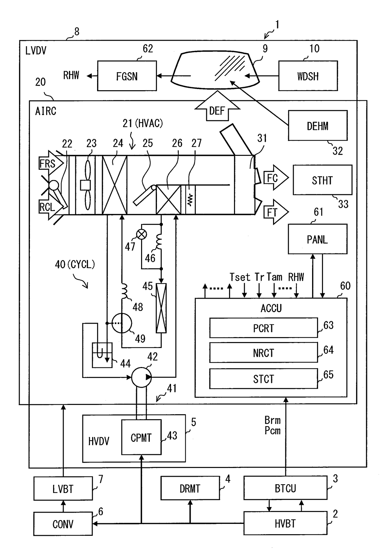
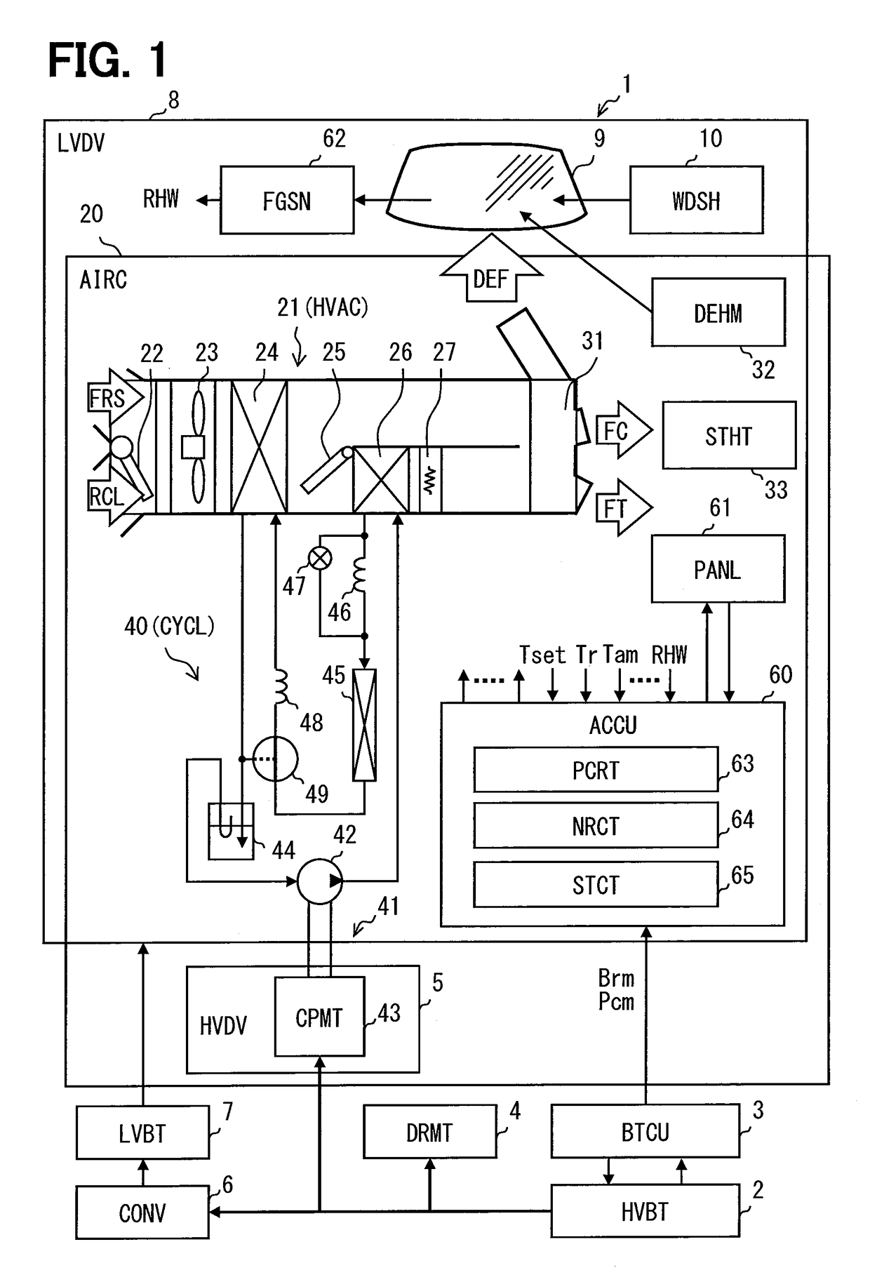
[0020]An electric vehicle system 1 illustrated in FIG. 1 is mounted on an electric vehicle. The electric vehicle is a vehicle which includes an electric driving system having both a storage battery and an electric motor. The electric vehicle may be a road traveling vehicle, a vessel, or an aircraft. A so-called electric car having only an electric driving system may serve as the electric vehicle. A hybrid vehicle which has, in addition to an electric driving system, an internal combustion engine system having both a fuel tank and an internal combustion engine may serve as the electric vehicle.
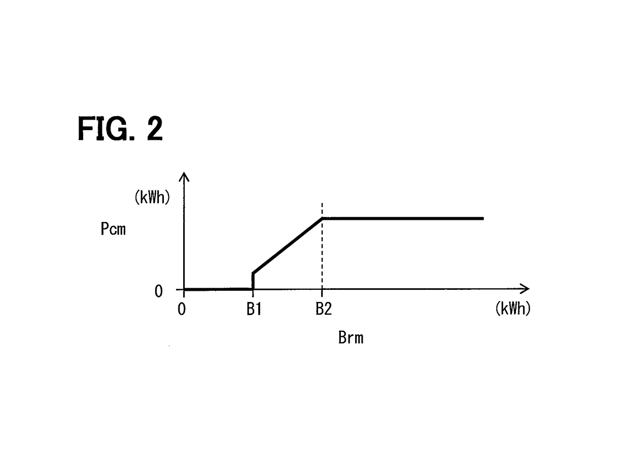
[0021]The electric vehicle system 1 has a high voltage battery (HVBT) 2. The high voltage battery 2 is a secondary battery. A lithium-ion battery or the like may serve as the high voltage battery 2. The high voltage battery 2 supplies relatively high voltage of several hundred volts. The high voltage battery 2 is charged through a stationary wide-area electric power grid or a ...
second embodiment
(Second Embodiment)
[0099]FIG. 4 illustrates an electric vehicle system 1A according to the second embodiment. In the present embodiment, a heat exchanger using a heating medium is provided as an example of an air heating device and a fog suppressor.
[0100]The heating medium heat exchanger 28 heats air, which flows through the air conditioning unit 21 and is blown to the cabin, using a cooling medium for cooling a device (HS) 29, as a heat source, mounted on a vehicle. The heating medium heat exchanger 28 is disposed in a state where the heating medium heat exchanger 28 heats at least a portion of air flowing through the air conditioning unit 21. The heating medium heat exchanger 28 is a portion of a cooling system for cooling the device 29. The cooling medium is a heat transfer fluid, such as water. The device 29 is a device generating heat and is provided by, for example, an electric device, an inverter circuit, or an internal combustion engine mounted on the vehicle.
[0101]When the ...
third embodiment
(Third Embodiment)
[0110]FIG. 6 illustrates an electric vehicle system 1B according to a third embodiment. In the present embodiment, a refrigeration circuit 340 is a cooler circuit in which only cooling can be performed. Even in the present embodiment, the same operational effects as those in the embodiment described above can be obtained.
(Other Embodiments)
[0111]Hereinbefore, preferred embodiments of the disclosure disclosed above are described. However, the disclosure is not limited to the embodiments described above and can be realized in various modifications. The configurations of the embodiments described above are only exemplifications and are not intended to limit the technical scope of the disclosure.
[0112]Means and functions provided by the control unit can be provided by, for example, only software, only hardware, or a combination thereof. The control unit may be constituted by, for example, an analog circuit.
[0113]In the embodiments described above, a heat pump circuit i...
PUM
 Abstract
Description
Claims
Application Information
 - R&D
- Intellectual Property
- Life Sciences
- Materials
- Tech Scout
- Unparalleled Data Quality
- Higher Quality Content
- 60% Fewer Hallucinations
Browse by: Latest US Patents, China's latest patents, Technical Efficacy Thesaurus, Application Domain, Technology Topic, Popular Technical Reports.
© 2025 PatSnap. All rights reserved.Legal|Privacy policy|Modern Slavery Act Transparency Statement|Sitemap|About US| Contact US: help@patsnap.com


