Appliance control apparatus and electrical appliance

a control apparatus and electrical appliance technology, applied in the direction of program control, testing/monitoring control system, instruments, etc., can solve the problems of increased standby power and secondary cell vdd, and achieve the effect of reducing standby power consumption and saving energy

Inactive Publication Date: 2006-01-19
HITACHI LTD
View PDF2 Cites 65 Cited by
  • Summary
  • Abstract
  • Description
  • Claims
  • Application Information

AI Technical Summary

Benefits of technology

[0014] According to the present invention, it is possible to reduce standby power consumed by the appliance control unit and electrical appliances, and to realize energy saving.

Problems solved by technology

The technique disclosed in Patent Reference 1 has a problem that, in an environment where there are a plurality of appliances, such as an illuminator, a TV set, an air conditioner and a camera, and radio signals are transferred via them, the secondary cells Vdd are always required and the standby power is increased.

Method used


Image

  • Appliance control apparatus and electrical appliance
  • Appliance control apparatus and electrical appliance
  • Appliance control apparatus and electrical appliance

Examples


Embodiment Construction

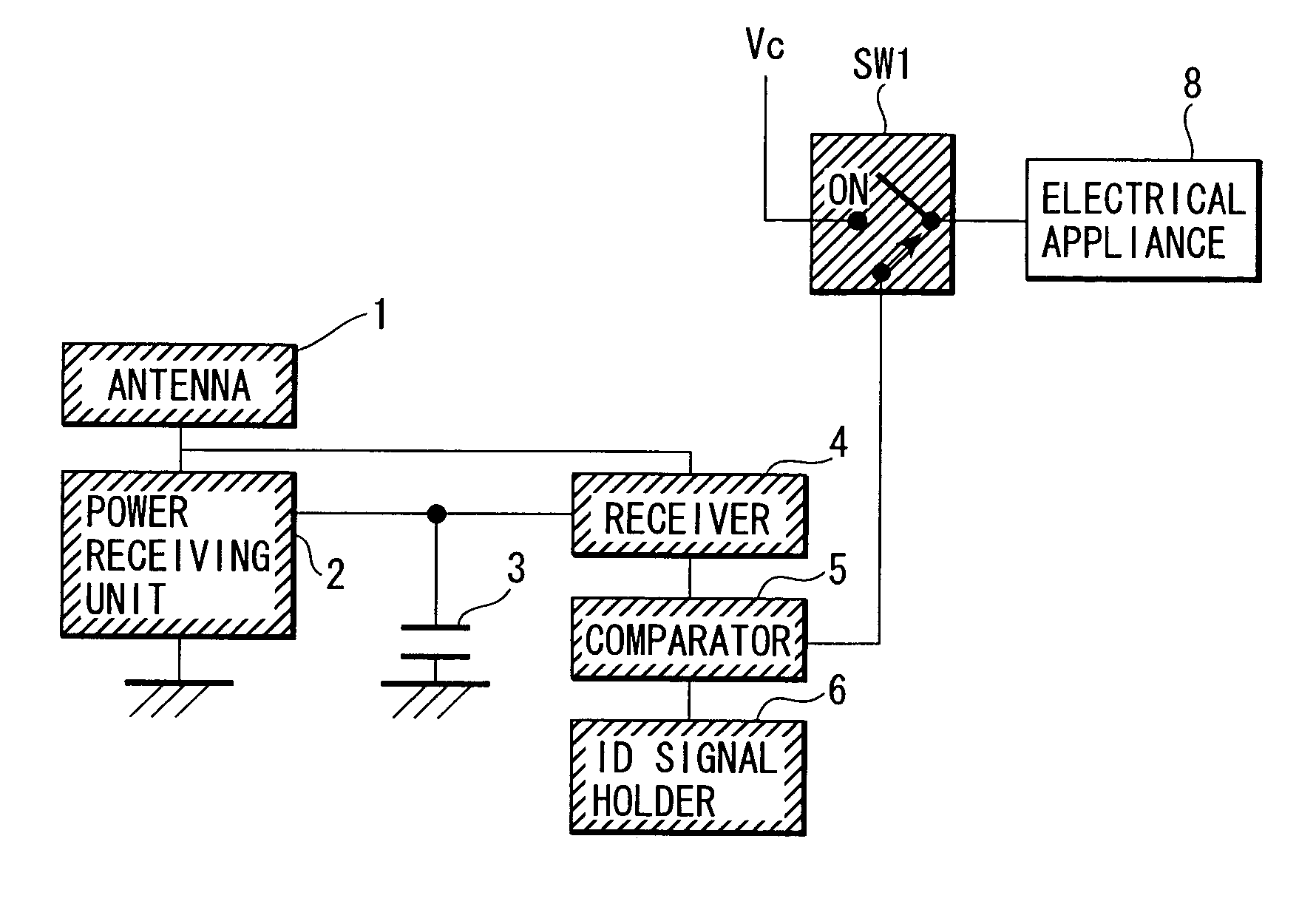
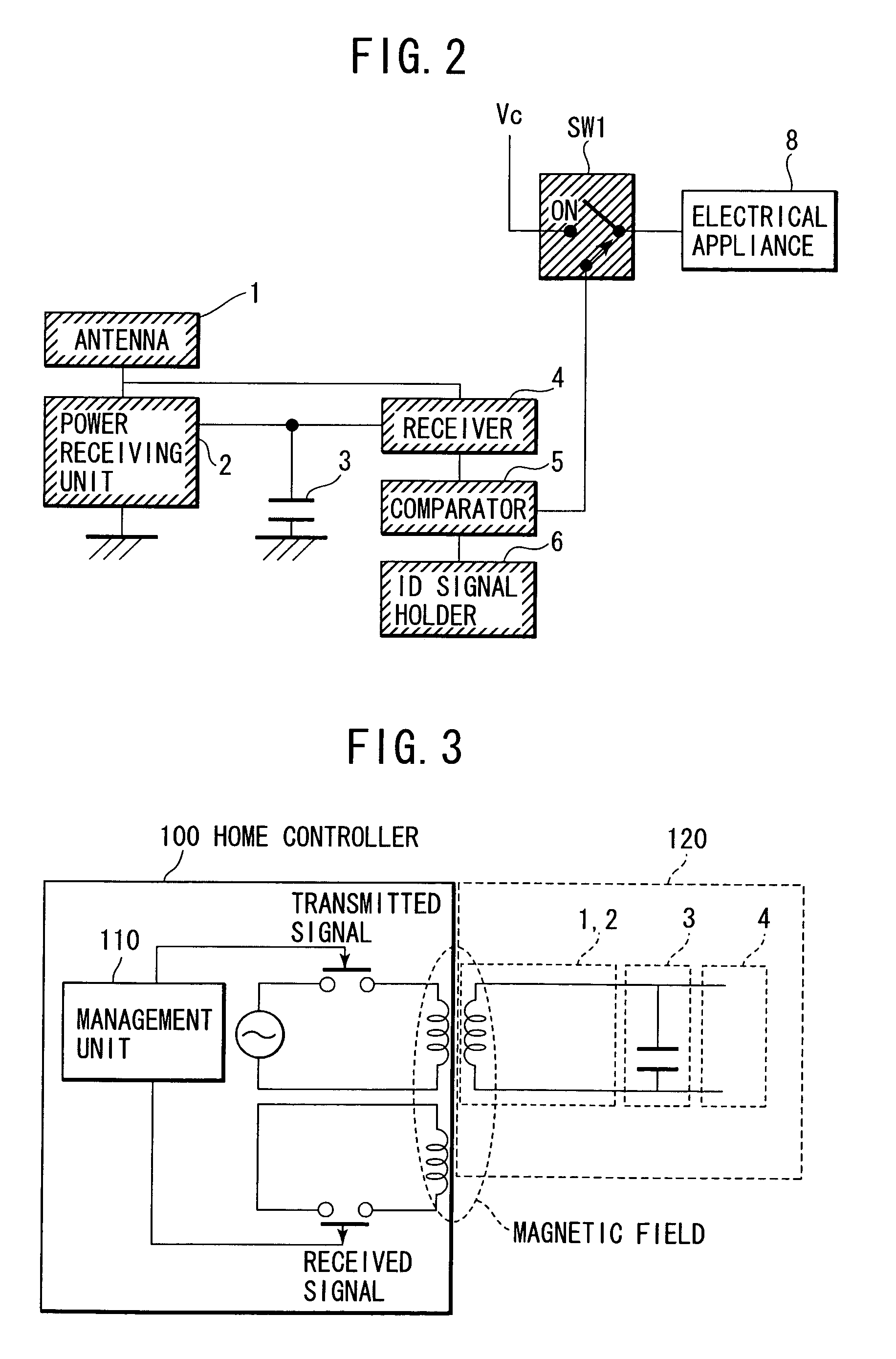
[0030] One embodiment of the present invention will be described in detail below with reference to FIGS. 1-14. This embodiment is concerned with a technique for cutting standby power in communications performed to monitor and control household electrical appliances, or to monitor and control various kinds of equipment used in buildings and homes, such as air conditioners, security apparatus, illumination units and elevators, or to monitor and control apparatus and equipment used in infrastructures, such as power, gas and water supply facilities.

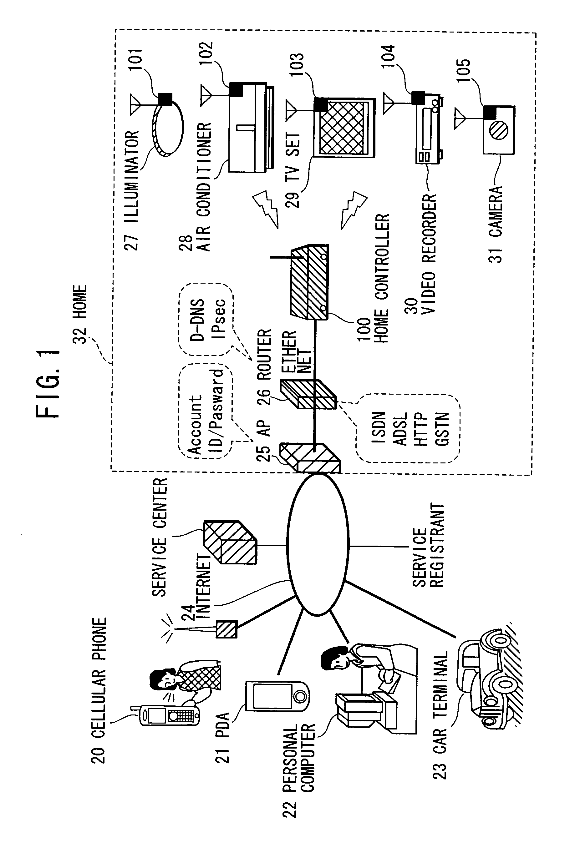
[0031]FIG. 1 illustrates an environment for use of household electrical appliances to which radio modules 101-105 are applied according to this embodiment. A user makes connection to the Internet 24 from a cellular phone 20, a PDA 21, a personal computer 22, a car terminal 23 or the like with a browser installed therein. In a home 32, a home controller 100 is connected to the Internet 24 via an access point (AP) 25, a router 26 or the like. ...


PUM


Abstract

Power is taken out from radio waves through an antenna and a power receiving unit. A signal receiver, a comparator, and an ID signal holder are operated with the taken-out power to compare an ID contained in a received signal with an ID read out from the ID signal holder. When both the ID's are matched with each other, a switch for a main power source is turned on. In trying to remotely operate household electrical appliances by utilizing the Internet that has become increasingly popular, standby power is consumed if the electrical appliances are kept in a standby state at all times. Since power is taken out from radio waves, the invention is able to cut the standby power in an environment where the radio waves are transferred via radio communication that is expected to be more and more prevalent in future.

Description

CLAIM OF PRIORITY [0001] The present application claims priority from Japanese application serial no. 2004-200009, filed on Jul. 17, 2004, the content of which is hereby incorporated by reference into this application. BACKGROUND OF THE INVENTION [0002] 1. Field of the Invention [0003] The present invention relates to an appliance control apparatus and an electrical appliance for use in homes. [0004] 2. Description of the Related Art [0005] In trying to remotely operate household electrical appliances by utilizing the Internet that has become increasingly popular, standby power is consumed if the household electrical appliances are kept in a standby state at all times. To solve such a problem by utilizing radio communication that seems to be more and more prevalent in future, JP,A 2001-197573 (hereinafter referred to as Patent Reference 1) discloses a technique of taking out power from radio waves, turning on a secondary cell Vdd, comparing a received signal with an ID signal, and t...

Claims


Application Information

Patent Timeline
Patent Type & Authority Applications(United States)
IPC IPC(8): H04Q1/00G08C19/00
CPCG08C17/02G08C2201/42
Inventor YOKOTA, TOSHIMISUZUKI, HIDEAKIYOSHIDA, SHOJIFUNAKI, SATORUSAITO, MASAHIKOKOJIMA, YASUYUKIKANOUDA, AKIHIKO
Owner HITACHI LTD
Why Eureka
Try Eureka