

Apparatus and method for standby power reduction of a flyback power converter
- Summary
- Abstract
- Description
- Claims
- Application Information
AI Technical Summary
Benefits of technology
Problems solved by technology
Method used
Image

Examples
Embodiment Construction
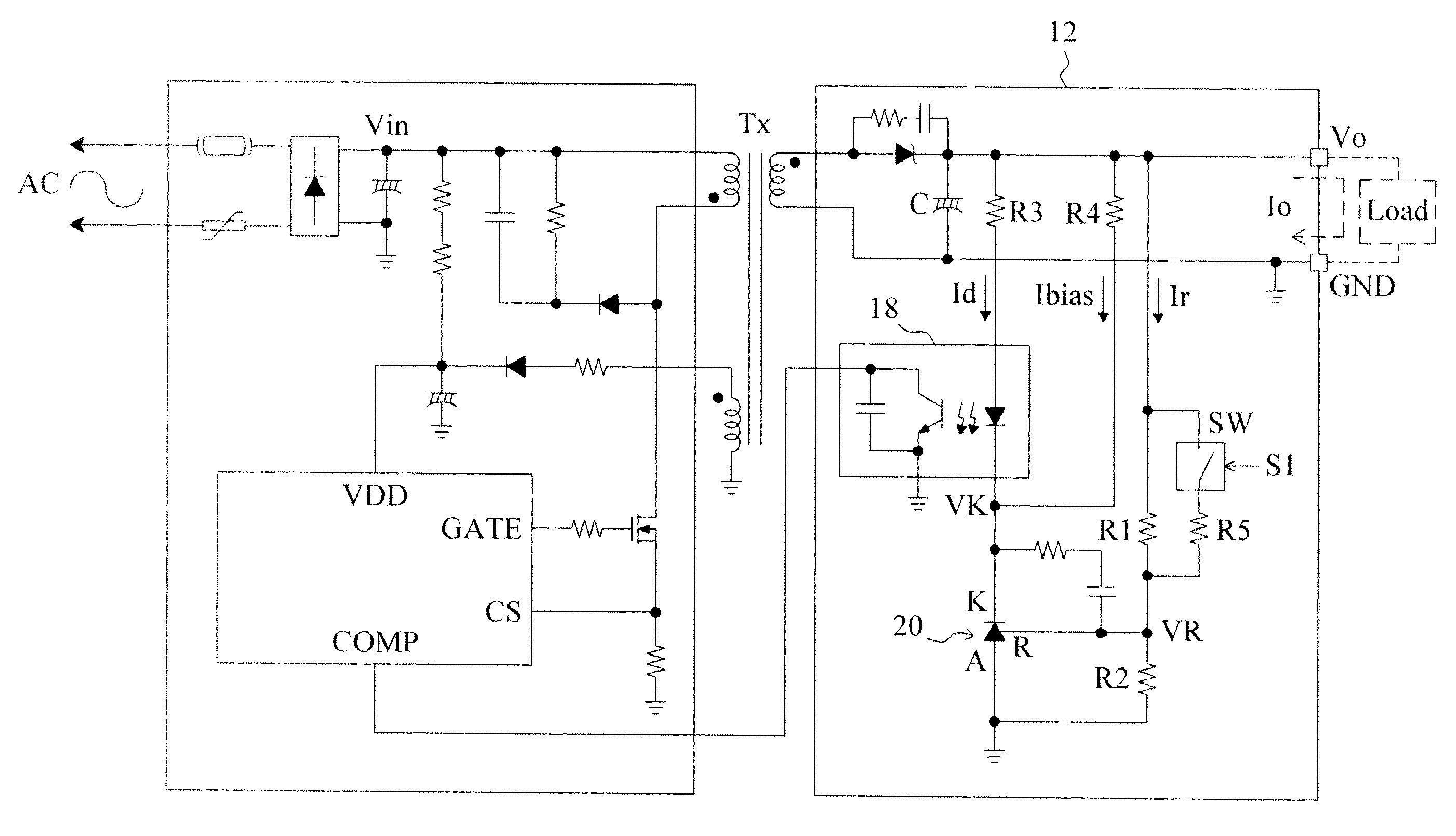
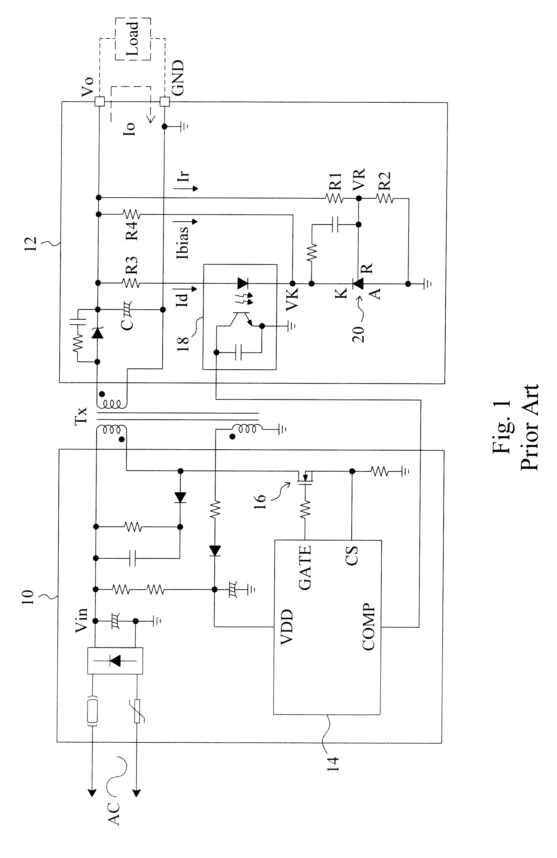
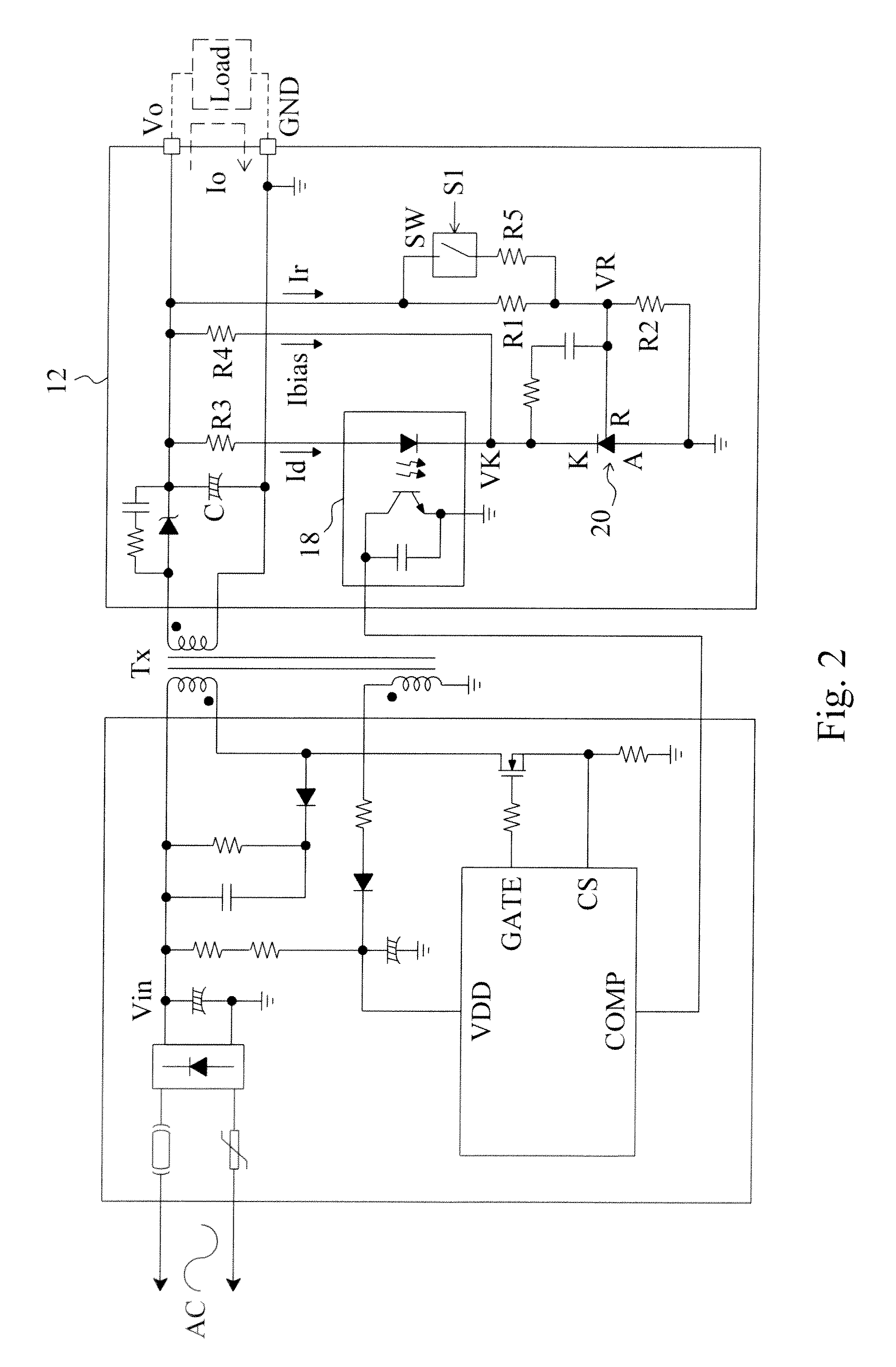
[0014]FIG. 2 is a circuit diagram of a first embodiment according to the present invention, which is designed with the same circuit structure as that of the conventional flyback power converter shown in FIG. 1 for illustrating the scope and features of the present invention, and has a switch-resistor network connected in parallel to the resistor R1. This added switch-resistor network includes a switch SW and a resistor R5 connected in series, and the switch SW is controlled by a sleep mode signal S1. The combination of the resistor R1 and the switch-resistor network has an equivalent resistance Req and thus the output voltage
Vo=VR×((Req+R2) / R2)=VR×(1+(Req / R2)). [Eq-5]
The ratio of the output voltage Vo to the reference voltage VR is determined by the voltage dividing ratio of the voltage divider established the equivalent resistor Req and the resistor R2. In normal operation, the switch SW is open and thus Req=R1. When the system enters a standby mode, the sleep mode signal S1 close...
PUM
 Abstract
Description
Claims
Application Information