Power supply having efficient low power standby mode

a power supply and low power technology, applied in the direction of electric variable regulation, process and machine control, instruments, etc., can solve the problem and achieve the effect of low standby loss of power converters

Inactive Publication Date: 2006-04-25
DELTA ELECTRONICS INC
View PDF6 Cites 28 Cited by
  • Summary
  • Abstract
  • Description
  • Claims
  • Application Information

AI Technical Summary

Benefits of technology

[0008]The present invention provides a general control approach to realize low standby loss for power converters.
[0010]With this means, moreover, in standby operation mode, a voltage hysteretic comparator functions as delta control of the output voltage. When the output voltage decreases to a low threshold of the voltage hysteretic comparator, the main circuit of the power converter operates and the output voltage increases. When the output voltage increases to a high threshold of the voltage hysteretic comparator, the main circuit of the power converter stops switching and the output voltage decreases. Therefore, in the standby operation mode, the power converter operates in the burst mode which results in a low standby loss.

Problems solved by technology

Therefore, in the standby operation mode, the power converter operates in the burst mode which results in a low standby loss.

Method used


Image

  • Power supply having efficient low power standby mode
  • Power supply having efficient low power standby mode
  • Power supply having efficient low power standby mode

Examples


Embodiment Construction

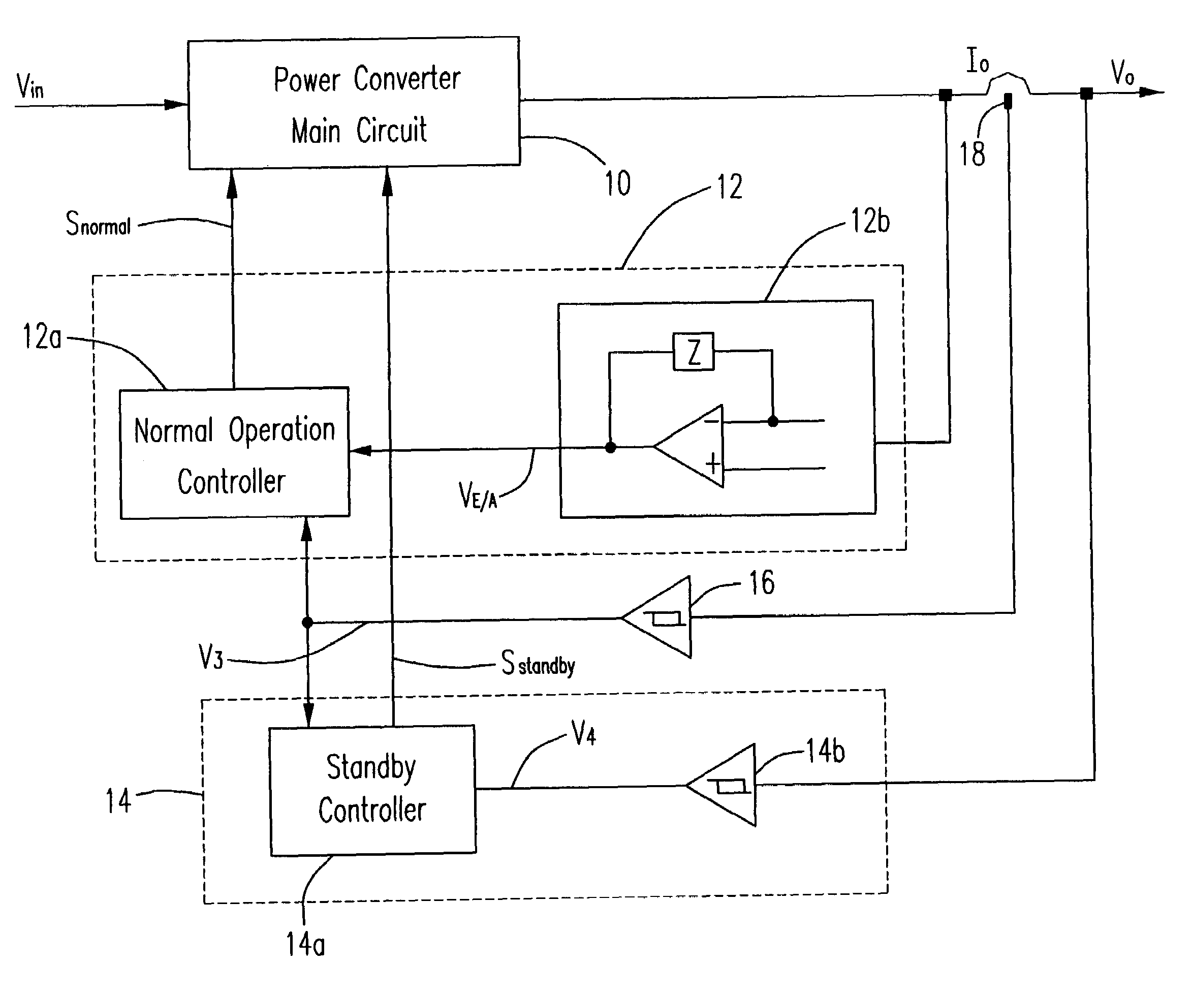
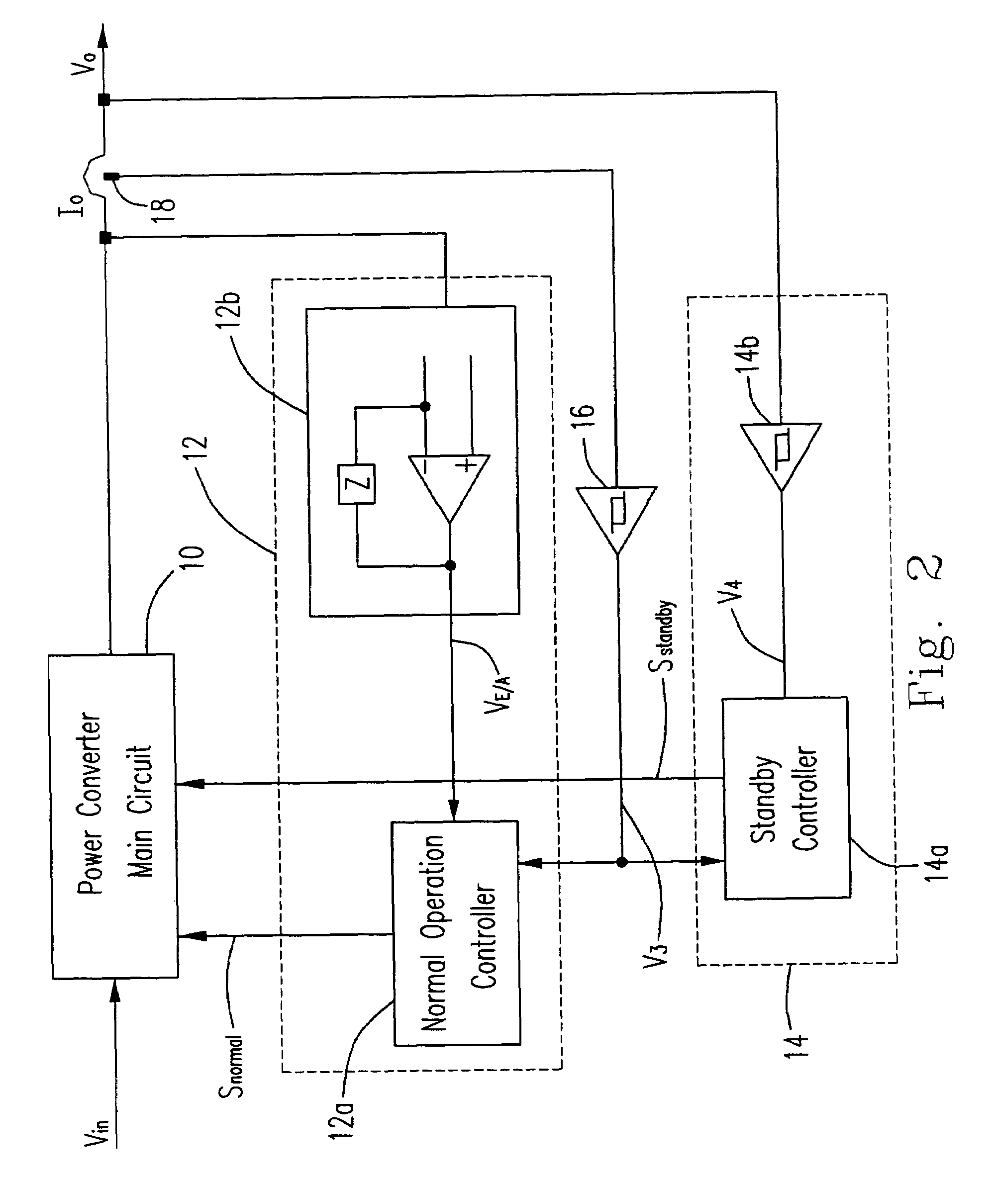
[0017]Please refer to FIG. 2. FIG. 2 is a block diagram of a power converter having a voltage hysteretic comparator and a loading hysteretic comparator according to the present invention. The power converter according to the present invention includes a main circuit 10 of a power converter with an input port Vin and an output port Vo, a main control circuit 12, a standby control circuit 14, a current sensor 18 and a loading hysteretic comparator 16. The main control circuit 12 includes a series arrangement of an error amplifier 12b and a normal operation controller 12a. The error amplifier 12b accepts the voltage Vo of the output port of the main circuit 10 and outputs a VE / A signal which is input to the normal operation controller 12a, whose output Snormal is used to control the main circuit 10. The standby control circuit 14 includes a series arrangement of a voltage hysteretic comparator 14b and a standby controller 14a. The voltage hysteretic comparator 14b accepts the voltage V...


PUM


Abstract

A power supply has a normal operation mode and a standby operation mode. The power supply includes a main circuit, a first control circuit, a second control circuit, and a switching controller. The main circuit has at least one output port for converting an input voltage into an output voltage at the output port. The first control circuit is used for controlling the main circuit under the normal operation mode. The second control circuit is used for controlling the main circuit under the standby operation mode. And, the switching controller processes a control signal to control the first control circuit and the second control circuit under either of the normal operation mode and the standby operation mode in response to a load status of the output port.

Description

FIELD OF THE INVENTION[0001]The present invention relates to a power supply and more particularly to a power supply having an efficient low power standby mode.BACKGROUND OF THE INVENTION[0002]Low standby loss is becoming a basic requirement for power supplies. Generally, there are two methods to achieve this requirement. One method is to reduce the operating frequency of a power converter, and the other one is to operate a power converter in a burst mode. When in the burst mode, the converter operates in several continuous switching cycles and then follows a no switching time period. With this means, the equivalent switching cycles in a certain time is low and thus the standby loss of the converter, mainly including the switching cycle related power loss, is low.[0003]Please refer to FIG. 1. FIG. 1 is a block diagram of a conventional power converter having a normal operation mode and a standby mode according to the prior art. The power converter circuit includes a main circuit 10, ...

Claims


Application Information

Patent Timeline
Patent Type & Authority Patents(United States)
IPC IPC(8): G05F1/40G05F1/66H02M3/28
CPCG05F1/66H02M3/28Y02B70/16H02M2001/0032H02M2001/0019H02M1/0019H02M1/0032Y02B70/10
Inventor GAN, HONGJIANKONG, QINGGANGZHANG, ALPHA J.CHANG, JIAN JUNG
Owner DELTA ELECTRONICS INC
Why Eureka
Try Eureka