LED Lamp Circuit

a led lamp and circuit technology, applied in the field of circuits, can solve the problems of affecting the operation and lifetime of the led lamp, the passive heat dissipation mechanism cannot provide satisfactory heat dissipation effect, and the heat generation of the led load is critical, so as to effectively prolong the lifetime of the led chip, the effect of active dissipation of the heat generated by the led load and better heat dissipation

Inactive Publication Date: 2010-07-22
NANKER GUANGZHOU SEMICON MFG
View PDF9 Cites 28 Cited by
  • Summary
  • Abstract
  • Description
  • Claims
  • Application Information

AI Technical Summary

Benefits of technology

[0029]The advantage of the present invention is that, the present invention comprises a rectifying-filtering circuit, an LED load, a constant current source, and a fan driving circuit, wherein an AC power passes through the rectifying-filtering circuit for rectifying and filtering to a DC power and so as to form an output terminal and a grounding terminal, wherein the LED lamp circuit is formed by cascading the LED load and the constant current source between the output terminal and the grounding terminal. The present invention innovatively combines the fan driving circuit with the LED load and the constant current source, so when the LED load is in operation, the fan driving circuit drives the fan to actively dissipate the heat generated by the LED load; therefore the present invention can provide better heat dissipation effect than the traditional passive ones to prevent the LED chip from operating under a high temperature condition and to effectively prolong the lifetime of the LED chip. In addition, the use of the active heat dissipation mechanism as disclosed here can reduce the size of the bulky heat sink to implement a LED lamp with a simpler structure, a smaller size, and longer lifetime while compared with the traditional LED lamps. The rectifying-filtering circuit converts the AC power into the DC power, even when the LED load operates under a high temperature condition for a period of time, the constant current source can prevent the current flowing to the LED lamp circuit from rising, and the voltage drop of the LED load is complemented by the constant current source to prolong the lifetime of the LED load. Besides, the constant current source is implemented as a stand alone element to conveniently replace other voltage regulating and over-current protection circuit to simplify the structure of the LED lamp circuit; therefore, the present invention can provide advantages such as simple structure, high efficiency, low power consumption, energy saving, and longer lifetime.
[0030]The present invention further comprises a voltage regulating circuit connected to an output of the rectifying-filtering circuit, wherein the voltage regulating circuit regulates the DC power generated by passing an AC power through the rectifying-filtering circuit to provide a constant DC power to the LED load and the constant current source cascaded between the output terminal and the grounding terminal. Therefore, the LED lamp circuit can provide constant and stable voltage output to the LED chips to facilitate the operation of the LED lamp with higher efficiency and longer lifetime; therefore the present invention not only provides constant current source but also provides voltage regulating function to achieve better performance and longer lifetime.
[0031]The present invention comprises a timer circuit connected with the voltage regulating circuit for providing a scheduled feedback signal to the voltage regulating circuit to change an output voltage of the voltage regulating circuit. The present invention innovatively combines the constant current source, the timer circuit, and the voltage regulating circuit with the LED load. When the LED lamp circuit starts operation, the LED load receives more power to output higher voltage with a higher brightness, when a predetermined time is reached, the timer circuit provides a scheduled feedback signal to the voltage regulating circuit to lower the output voltage of the voltage regulating circuit; therefore, the LED lamp outputs a lower voltage with a dimmer brightness. For LED lamps such as the street lamp, garden light and porch light, the LED lamp should be as bright as possible to provide good illumination when the night comes, but when it's late in the night, the LED lamp could be dimmer to save power. On the other hand, the voltage regulating circuit can output a lower voltage when it starts operation, when a predetermined time is reached, the timer circuit provides a scheduled feedback signal to the voltage regulating circuit to increase the output voltage of the voltage regulating circuit; then the LED lamp outputs a normal voltage with a high brightness. Therefore, the present invention can control the output voltage of the LED lamp for different time periods respectively to change the brightness of the LED lamp and to save power.
[0032]The present invention also comprises a shortage protection circuit connected between an input of the AC power supply and the rectifying-filtering circuit to provide over-current and over-voltage protection.

Problems solved by technology

It is common to use a plurality of high power LED chips in one lamp to achieve desirable brightness for lighting applications; however, the heat generated by the plurality of LED chips has affected the operation and lifetime of the LED lamp.
Therefore, heat dissipation has become a critical issue for promoting LED lighting, particularly for promoting the high power LED lamps.
Generally, traditional LED lamps adopt passive heat dissipation mechanism, in which a heat sink or the like is used for dissipating the heat generated by LED chips, since the heat sink requires much space to achieve better dissipating effects, the traditional LED lamps tend to be bulky and have complicated heat dissipation mechanism, furthermore, the passive heat dissipation mechanism can not provide satisfactory of heat dissipation effect.
As described above, the LED lamp circuit could have disadvantages such as a large number of circuit elements, a complicated circuit structure, and high power consumption. FIG. 1 illustrates a traditional voltage regulating circuit for an isolated switching mode power supply, in which the word “isolated” means the grounding terminals for each side of the transformer is independent, in this circuit, the output voltage at the output terminal remains stable; however, when the LED operates under a high temperature condition for a period of time, the threshold voltage of the LED could drop, which leads to a higher operating current.
Therefore, in practical applications of a voltage regulating circuit, when the supplied voltage remains stable, the LED could be damaged by the increasing operating current. FIG. 2 illustrates a prior art non-isolated constant current power supply.
Although in this circuit the output current from the output terminal remains constant, in cases of multiple LED loads connected in parallel, the output current could be unevenly distributed in different branches of the LED chips, when LED chips in one branch are damaged accidentally, all other branches could be damaged as well.
Furthermore, the circuits described above usually are implemented with a large number of circuit elements that could consume a lot of power, particularly the power transistor used in these applications, which can make it difficult for the LED lamp circuit to save power as it intends to.
When a negative voltage is applied between the gate terminal and the source terminal, the channel is cut off and the current is zero, the voltage of the gate terminal is defined as the open circuit voltage; however, when the concentration of the channel is too high and the depth of the channel is too deep, it becomes difficult to cut off the channel current by applying negative voltage to the gate terminal.
For the depletion type MOSFET, when the voltages at the gate terminal and the source terminal are zero, the source terminal is switched on and has a constant leak current, making it less popular than the enhancement-type MOSFET for logic applications and for stand-alone components.

Method used


Image

  • LED Lamp Circuit
  • LED Lamp Circuit
  • LED Lamp Circuit

Examples


first embodiment

[0046]As shown in FIG. 7, a LED lamp of the present invention is a high power LED lamp with a fan for use in the ceiling, and the LED lamp comprises a LED heat sink 20, a metal heat dissipation element 30, a heat dissipating fan 40, a case 50, a driving circuit board 60, a reflector cup 70, a fastener 34, a ring element 81, a spring plate 82, and a gripper 83. The LED heat sink 20 is fixed with a plurality of high power LED chips 10 (i.e. LED load 3 in FIG. 8) thereon. The perimeter of each LED chip 10, on the LED heat sink 20, fixes with a coffer 21 filled with phosphor and optical resin. The coffer 21 retains the phosphor and the optical resin during the manufacturing process to improve the production efficiency. A protection cover 90 covers the LED heat sink 20 along with the LED chip 10. The metal heat dissipation element 30 is formed as a fin-like heat sink. The case 50 is configured with ventilation holes 51 thereon. The metal heat dissipation element 30 is connected with the ...

second embodiment

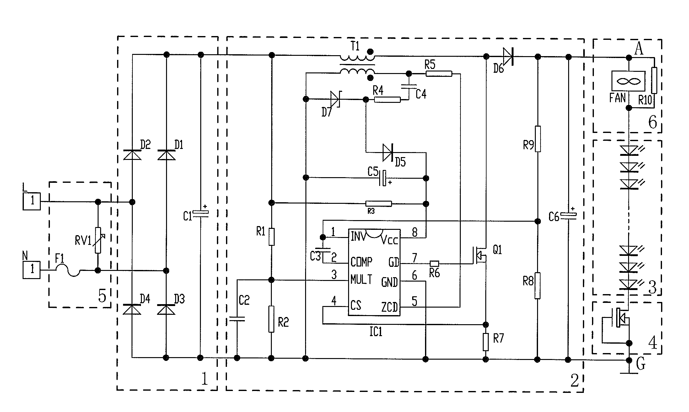
[0058]As shown in FIG. 4, this embodiment is different from the first embodiment in that the LED load 3 comprises four sets of mutually cascaded LED chips. Each set of LED chips is connected with a constant current source 4 in series, then the four sets of LED chips are connected in parallel. The four sets of LED chips are cascaded with the fan driving circuit 6. Therefore, there are four constant current sources 4 in this embodiment. In this embodiment, the number of LED chips for each set is calculated in the same way as that of the first embodiment.

[0059]The rest of this embodiment is same as that of the first embodiment.

third embodiment

[0060]As shown in FIG. 5, this embodiment is different from the first embodiment in that the LED load 3 comprises four sets of mutually cascaded LED chips. Each set of LED chips is connected with other sets of LED chips in parallel, then the four sets of LED chips are connected with the fan driving circuit 6 and the constant current source 4 in series; therefore, there is only one constant current source 4 in this embodiment.

[0061]The rest of this embodiment is same as that of the first embodiment.


PUM


Abstract

The present invention discloses a high power LED lamp circuit with a fan provides advantages such as simple structure, high efficiency, low power consumption, energy saving, and longer lifetime. The LED lamp circuit comprises a rectifying-filtering circuit (1), an LED load (3), an output terminal (A) and a grounding terminal (G) for providing a DC power generated by passing an AC power through the rectifying-filtering circuit (1), the high power LED lamp circuit with a fan further comprises a constant current source (4), a fan driving circuit (6); the lamp circuit is formed by cascading the LED load (3), the constant current source (4) between the output terminal (A) and the grounding terminal (G), the LED lamp circuit is widely applicable in various kinds of LED lamps.

Description

BACKGROUND OF THE INVENTION[0001]1. Field of the Invention[0002]The present invention relates to a circuit for use with an LED lamp.[0003]2. Description of the Related Art[0004]Presently more LED applications are emerging, which includes LED lamps used in indoor lighting. It is common to use a plurality of high power LED chips in one lamp to achieve desirable brightness for lighting applications; however, the heat generated by the plurality of LED chips has affected the operation and lifetime of the LED lamp. Therefore, heat dissipation has become a critical issue for promoting LED lighting, particularly for promoting the high power LED lamps. Generally, traditional LED lamps adopt passive heat dissipation mechanism, in which a heat sink or the like is used for dissipating the heat generated by LED chips, since the heat sink requires much space to achieve better dissipating effects, the traditional LED lamps tend to be bulky and have complicated heat dissipation mechanism, furthermo...

Claims


Application Information

Patent Timeline
Patent Type & Authority Applications(United States)
IPC IPC(8): H02J1/00H05B37/02H05B44/00
CPCY02B20/347H05B33/0815Y02B20/30H05B45/3725
Inventor WU, WEI-KUO
Owner NANKER GUANGZHOU SEMICON MFG
Why Eureka
Try Eureka