Sensing device and electronic apparatus

a technology of sensing device and electronic equipment, applied in power management, instruments, wireless communication, etc., can solve the problems of increasing cost, increasing power consumption, and not achieving cost increase, and achieve the effect of suppressing power consumption

Active Publication Date: 2012-01-26
SEIKO EPSON CORP
View PDF4 Cites 65 Cited by
  • Summary
  • Abstract
  • Description
  • Claims
  • Application Information

AI Technical Summary

Benefits of technology

[0045]According to this configuration, it is possible to provide an electronic apparatus with power consumption suppressed.

Problems solved by technology

However, the power consumption increases because other components such as a sensor, an analog front end (AFE), an AD converter (ADC) continue to operate.
However, cost increases because the two motion sensors having the equivalent functions are prepared regardless of the fact that the motion sensors operate only exclusively.
Since it is unnecessary to separately prepare a sensor, the problem of an increase in cost does not occur.
Therefore, when the operation mode of the motion sensor is the partial operation mode, power consumption of the sensing device is small compared with that during the overall operation mode.
In the switching from the overall operation mode to the partial operation mode, if the overall operation mode is shifted to the partial operation mode by mistake, measurement data cannot be obtained from the sensor.

Method used


Image

  • Sensing device and electronic apparatus
  • Sensing device and electronic apparatus
  • Sensing device and electronic apparatus

Examples


first embodiment

1. First Embodiment

[0064]A first embodiment of the invention is explained with reference to FIGS. 1 to 5.

1.1. Configuration of a Sensor Module

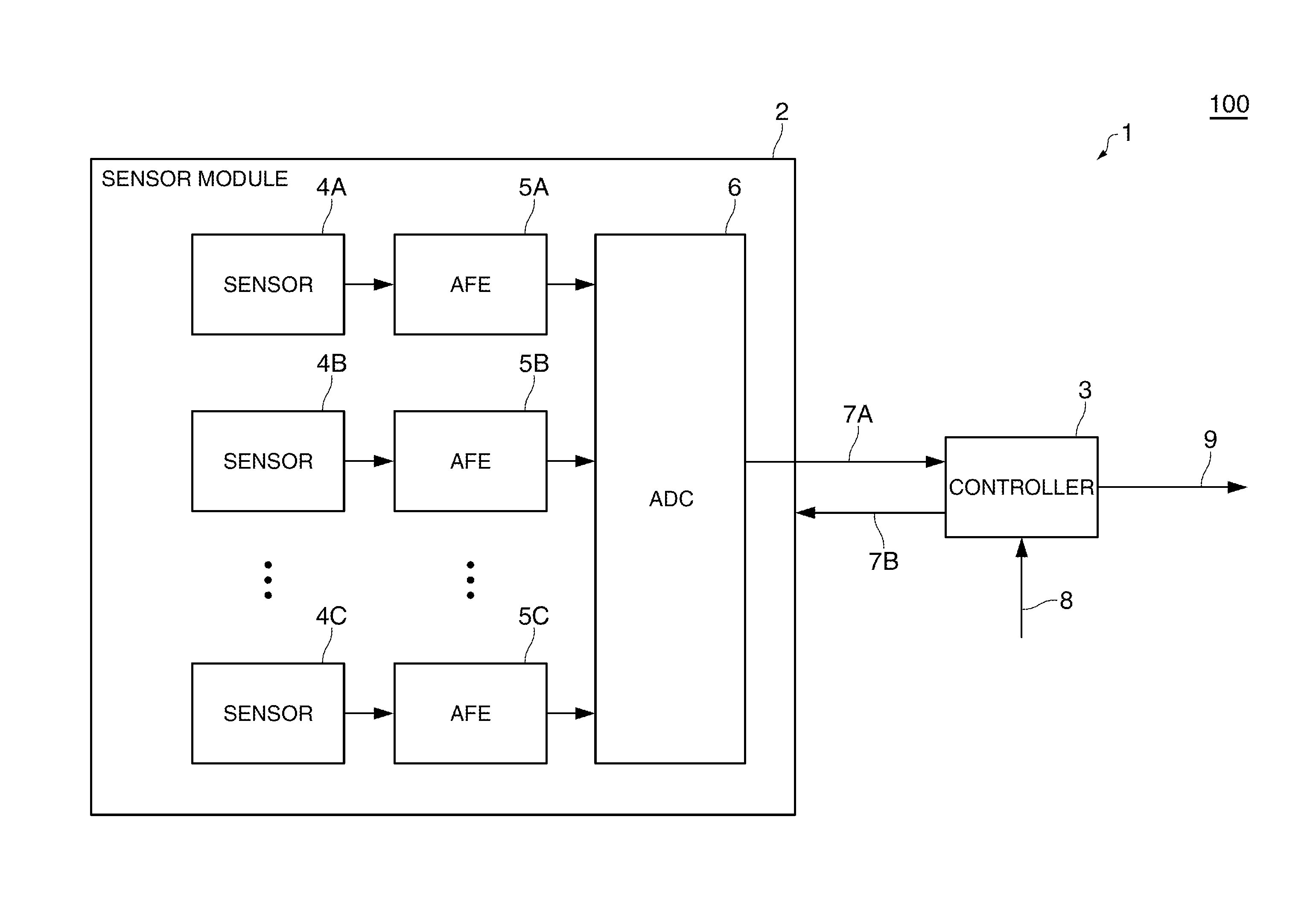
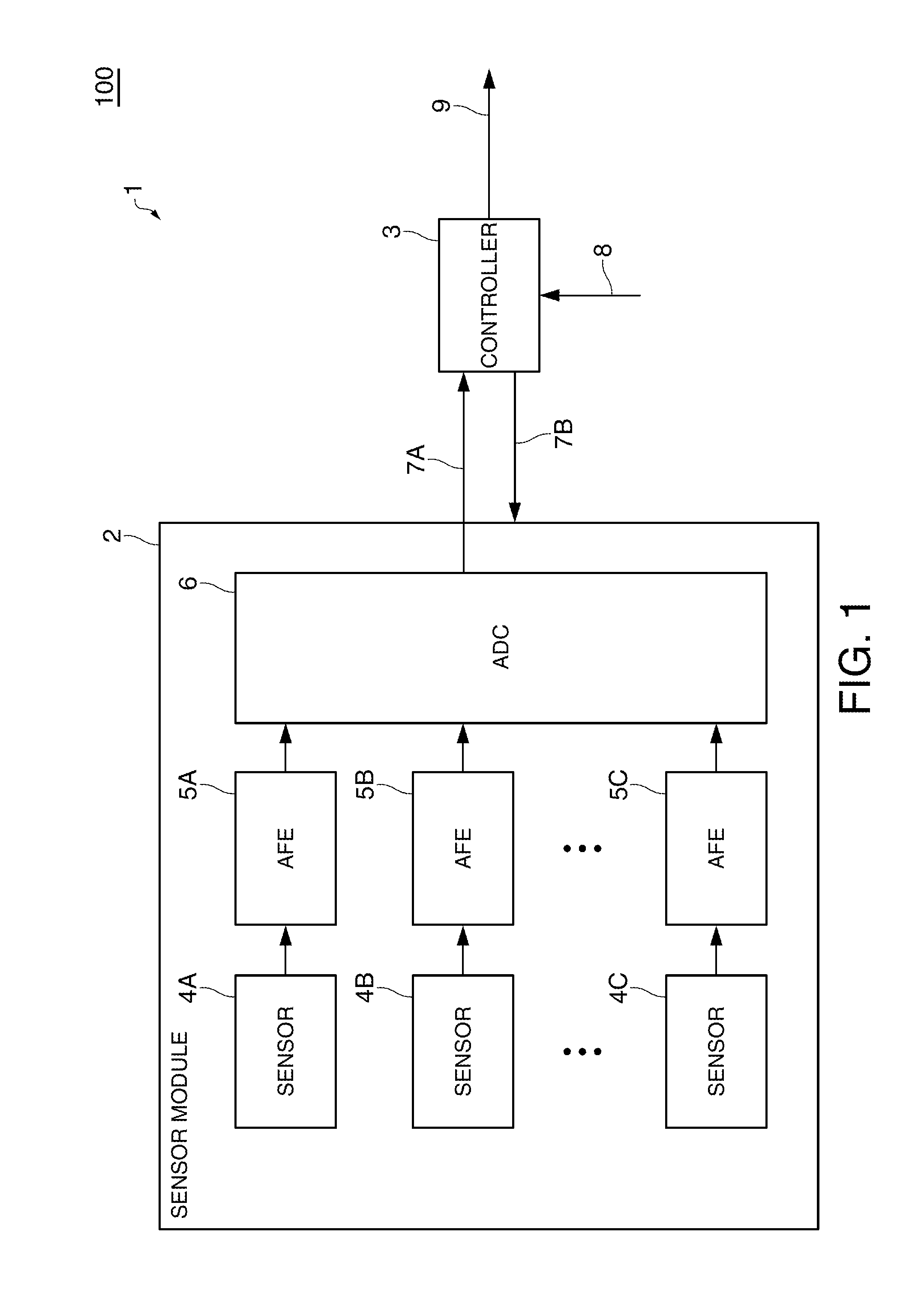
[0065]FIG. 1 is a block diagram of a part 1 of a sensing device 100. The sensing device 100 in the first embodiment includes at least a sensor module 2 and a controller 3.

[0066]The sensor module 2 includes a group of sensors 4A to 4C, which are plural sensors. The sensor module 2 may include analog front ends (AFEs) 5A to 5C that perform signal amplification and the like and an AD converter (ADC) 6 that converts an analog amount into a digital value.

[0067]In this embodiment, at least one of the group of sensors 4A to 4C is a motion sensor. The motion sensor indicates a sensor that detects motion such as an acceleration sensor or a gyro sensor.

[0068]In FIG. 1, for example, the sensor 4A may be the motion sensor and the other sensors 4B and 4C may be any one of or a combination of a temperature and humidity sensor, a pressure sensor, a magnetic ...

second embodiment

2. Second Embodiment

[0113]A second embodiment of the invention is explained with reference to FIGS. 6 to 11. In the second embodiment, an auxiliary sensor module is used in addition to the configuration in the first embodiment. By using the auxiliary sensor module, an operation mode of a sensor module can be switched to a stop operation mode for stopping at least a part of a group of sensors. When the operation mode is switched to the stop operation mode, power consumption can be suppressed. As the auxiliary sensor module, an inexpensive sensor can be selected and a problem of an increase in cost does not occur. Even when the group of sensors of the sensor module does not include a motion sensor, low power consumption can be realized without changing design.

2.1. Configuration of the Auxiliary Sensor Module

[0114]FIG. 6 is a block diagram of a part 1A of a sensing device 100A. An auxiliary sensor module 202 in this embodiment is explained with reference to FIG. 6. Components same as t...

third embodiment

3. Third Embodiment

[0143]A third embodiment of the invention is explained with reference to FIGS. 1 to 4, FIGS. 9 and 10, and FIG. 12. In the third embodiment, a data generating unit generates output data on the basis of an output from a group of sensors. When the output data is generated, a rate for generating the output data is switched on the basis of a mode control signal to further reduce power consumption.

3.1. Main Configuration of a Sensing Device

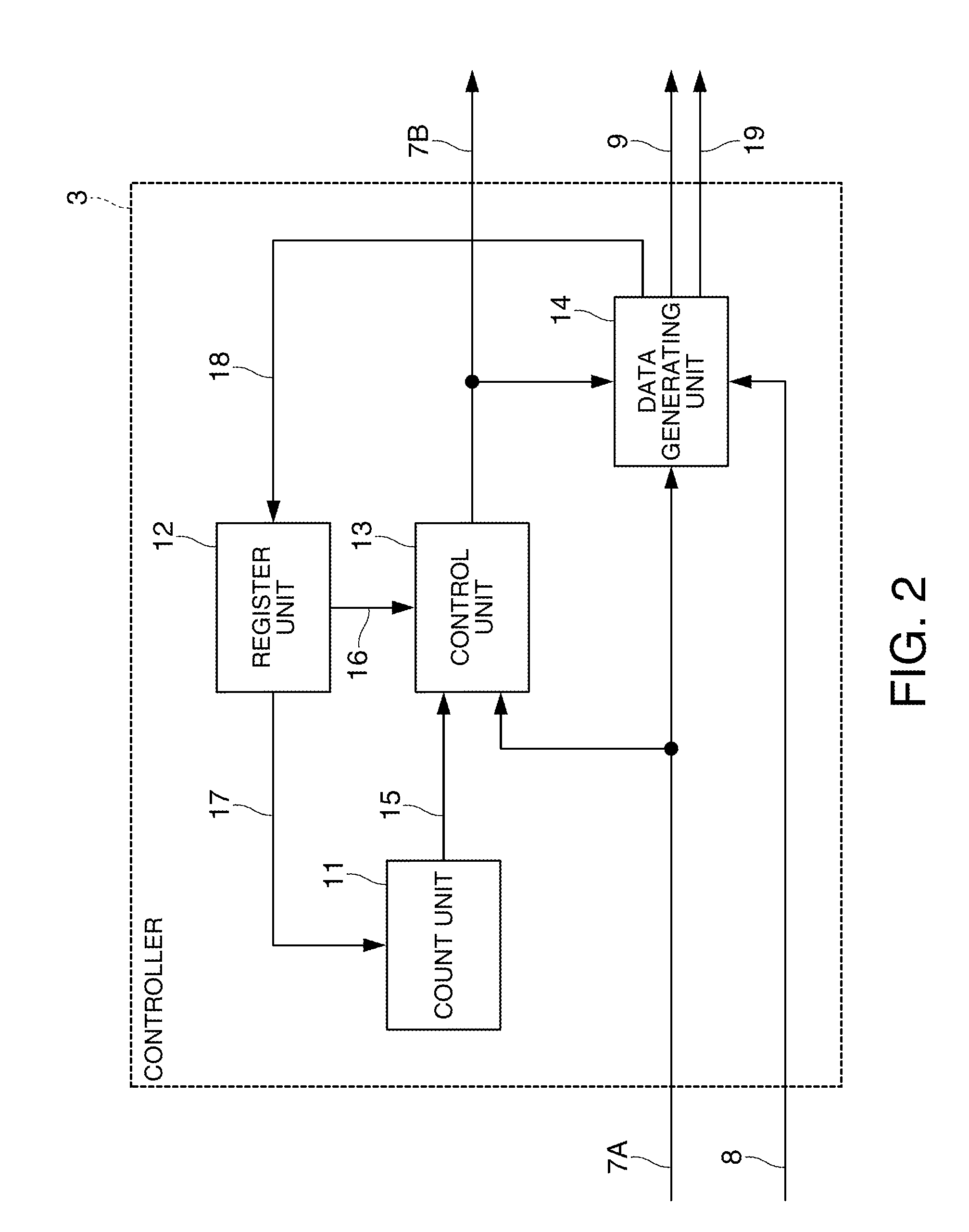
[0144]A sensing device in the third embodiment always includes a data generating unit. Otherwise, the sensing device may be the same as that in the first embodiment or the second embodiment. In the following explanation, it is assumed that the sensing device has a configuration same as that in the first embodiment. The configuration of a part of the sensing device 100 is shown in FIG. 1. The configuration of the controller 3 is shown in FIG. 2. In the third embodiment, the controller 3 always includes the data generating unit 14 and ...


PUM


Abstract

A sensing device includes: a sensor module that includes a group of sensors, at least one of which is set as a motion sensor, and can switch an operation mode to an overall operation mode in which all of the group of sensors operate and a partial operation mode in which a part of the sensors including the at least one sensor set as the motion sensor operate; and a control unit that controls the switching of the operation mode of the sensor module on the basis of an output from the motion sensor.

Description

BACKGROUND[0001]1. Technical Field[0002]The present invention relates to a sensing device, an electronic apparatus, and the like.[0003]2. Related Art[0004]Some sensor module includes a sensor that detects the motion of a gyro sensor, an acceleration sensor, or the like (a motion sensor). For example, a sensor module disclosed in JP-A-2009-134071 (Patent Document 1) converts a signal from a motion sensor and outputs the signal at a predetermined interval. In this invention, an embodiment in which signal processing is performed without using a CPU to suppress power consumption is disclosed. However, the power consumption increases because other components such as a sensor, an analog front end (AFE), an AD converter (ADC) continue to operate.[0005]In JP-A-2008-175771 (Patent Document 2), two motion sensors having different measurement ranges and equivalent functions are prepared and switched according to a situation, whereby an increase in current consumption can be suppressed. However...

Claims


Application Information

Patent Timeline
Patent Type & Authority Applications(United States)
IPC IPC(8): G06F1/32
CPCG01P13/00H04W52/0254G01P15/00G06F1/3206
Inventor CHINO, TAKETO
Owner SEIKO EPSON CORP
Why Eureka
Try Eureka