Pellicle support frame, pellicle, method for manufacturing pellicle support frame, and exposure original plate and exposure device employing pellicle

a technology of pellicle and support frame, which is applied in the direction of microlithography exposure apparatus, instruments, photomechanical treatment, etc., can solve the problems of deteriorating filter cover, difficult air to pass through the filter, and relatively long time to evacuate to the inside of the pellicle, etc., to achieve the effect of easy detachable filter

Active Publication Date: 2021-03-18
MITSUI CHEM INC
View PDF0 Cites 2 Cited by
  • Summary
  • Abstract
  • Description
  • Claims
  • Application Information

AI Technical Summary

Benefits of technology

[0008]It is an object of the present invention to solve the above-mentioned problems and to provide a support frame in which a vent hole is provided with an easily detachable filter, and in which a pellicle film for extreme ultraviolet light lithography can be provided, a pellicle in which a pellicle film for extreme ultraviolet light lithography is provided in support frame, a method for manufacturing support frame, and an exposure pattern plate using these support frames and a exposure device.
[0258]In the embodiment, since no adhesive is required for fixing the filter, the generation of outgas from the adhesive is reduced, and contamination is suppressed in a region in the space formed by the pattern plate and the pellicle in which the EUV light is irradiated. It is possible to suppress fogging of the lenses of optical system of the exposure device due to outgassing from the adhesives, exposure defects, and light deficiency.

Problems solved by technology

In the case where an area of the filter on the support unit of the pellicle is small when an inner space of a lithography apparatus using a EUV pellicle is evacuated, the air is difficult to pass through the filter, and it takes relatively long time to evacuate to the inside of the pellicle.
On the other hand, the filter covering the vent hole is deteriorated due to exposure of the EUV light, so it needs to be replaced, but it is difficult to replace the filter integrated with the pellicle frame.
Outgases cause deposits on the surface of the photomask or cause fogging of the lens optical system exposure measures, resulting in poor exposure or insufficient light.
In the conventional pellicle in which one vent hole is covered with one filter, the replacement of the filter is complicated.
Therefore, inside the support frame 111F for pellicle (the cross-sectional directions B and D), although the exposure area of the end surface of the filter 30 is small, it may be exposed to the scattered and diffracted EUV light, and there is a possibility that it cause light degradation.
Outgassing caused by photodegradation may cause contamination to deposit on the surface of the pattern plate.

Method used


Image

  • Pellicle support frame, pellicle, method for manufacturing pellicle support frame, and exposure original plate and exposure device employing pellicle
  • Pellicle support frame, pellicle, method for manufacturing pellicle support frame, and exposure original plate and exposure device employing pellicle
  • Pellicle support frame, pellicle, method for manufacturing pellicle support frame, and exposure original plate and exposure device employing pellicle

Examples


embodiment 1

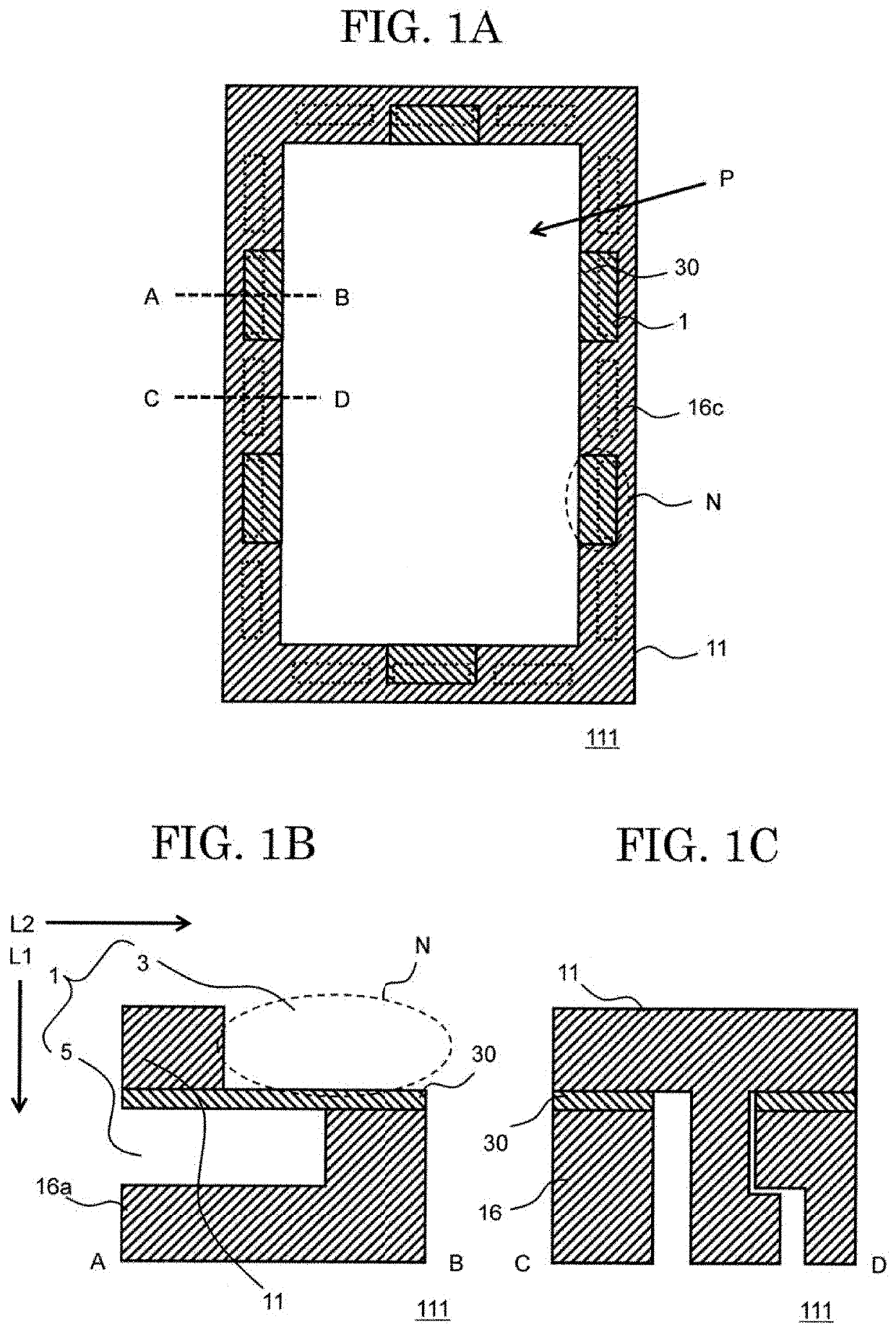
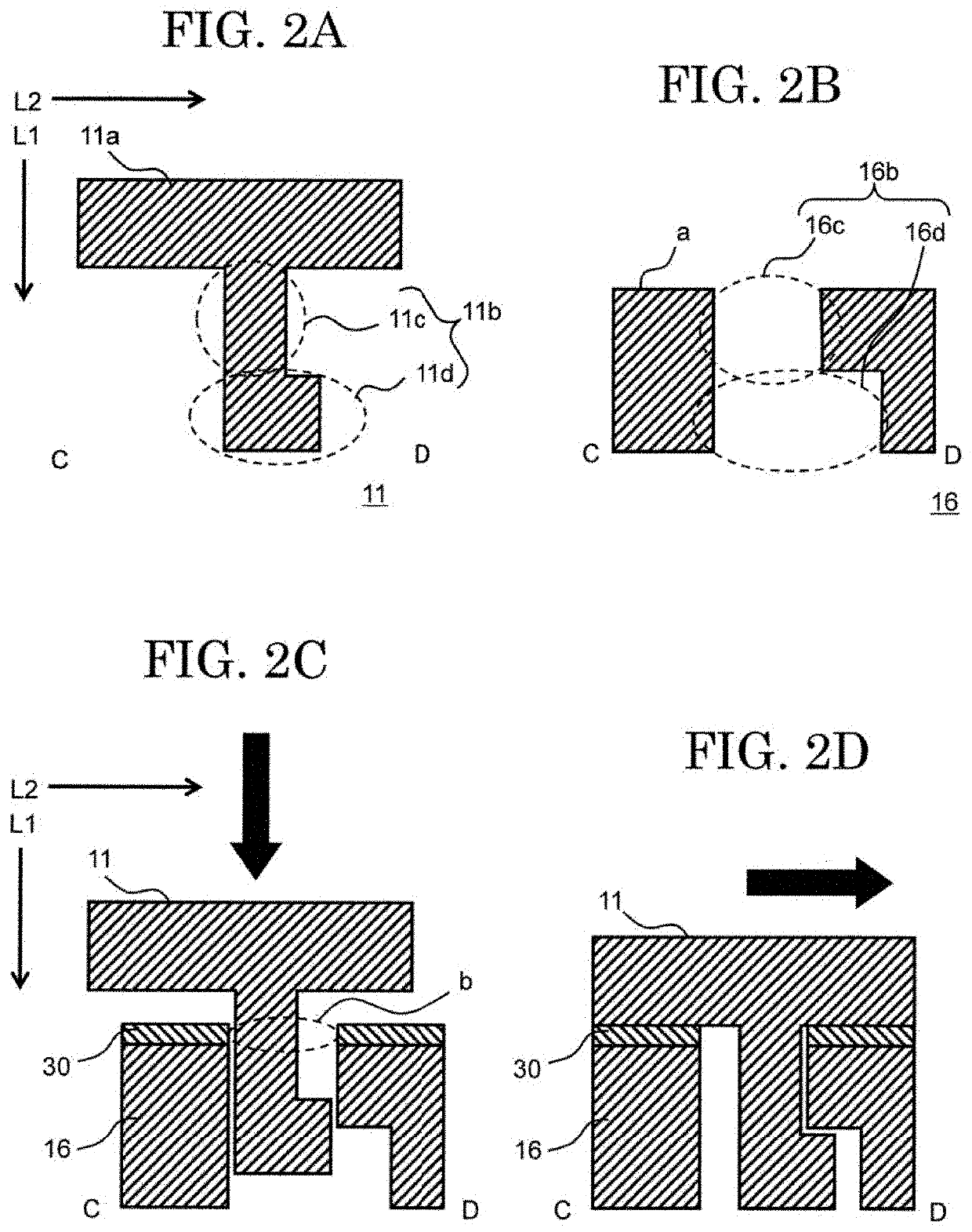
[0147]FIGS. 1A to 1C are schematic diagrams of a support frame 111 for pellicle according to an embodiment of the present invention. FIG. 1A is a schematic diagram of the support frame 111 for pellicle viewed in the plane direction of the pattern plate (mask) where the support frame 111 for pellicle is arranged from the side where the pellicle film is arranged. The “plane direction of pattern plate” is a direction intersecting the plane of the pattern plate, in the present embodiment, a direction substantially perpendicular to the plane of the pattern plate. FIG. 1B is a cross-sectional view of the support frame 111 for pellicle in the line segment AB of FIG. 1A, and FIG. 1C is a cross-sectional view of the support frame 111 for pellicle in the line segment CD of FIG. 1A. FIGS. 2A to 2D are schematic diagrams illustrating the details of a first support frame part 11 and a second support frame part 16 constituting the support frame 111 for pellicle. FIG. 2A is a schematic diagram ill...

embodiment 2

[0159]In the first embodiment described above, the first body part 11a and the first engaging portion 11b are integrally molded, or the first support frame part 11 in which the first engaging portion 11b is connected to the first body part 11a is used, however, the support frame for pellicle and the pellicle related to the present invention are not limited thereto. Examples of constituting the first support frame part and the second support frame part by laminating a plurality of plate-shaped members will be described as Embodiment 2. Hereinafter, a configuration different from that of Embodiment 1 will be described in particular, and a description of the same configuration as that of Embodiment 1 will be omitted.

[0160]FIGS. 4A to 4C are schematic diagrams of a support frame 111A for pellicle according to an embodiment of the present invention. FIG. 4A is a schematic diagram of the support frame 111A for pellicle viewed in the plane direction of the pattern plate where the support f...

embodiment 3

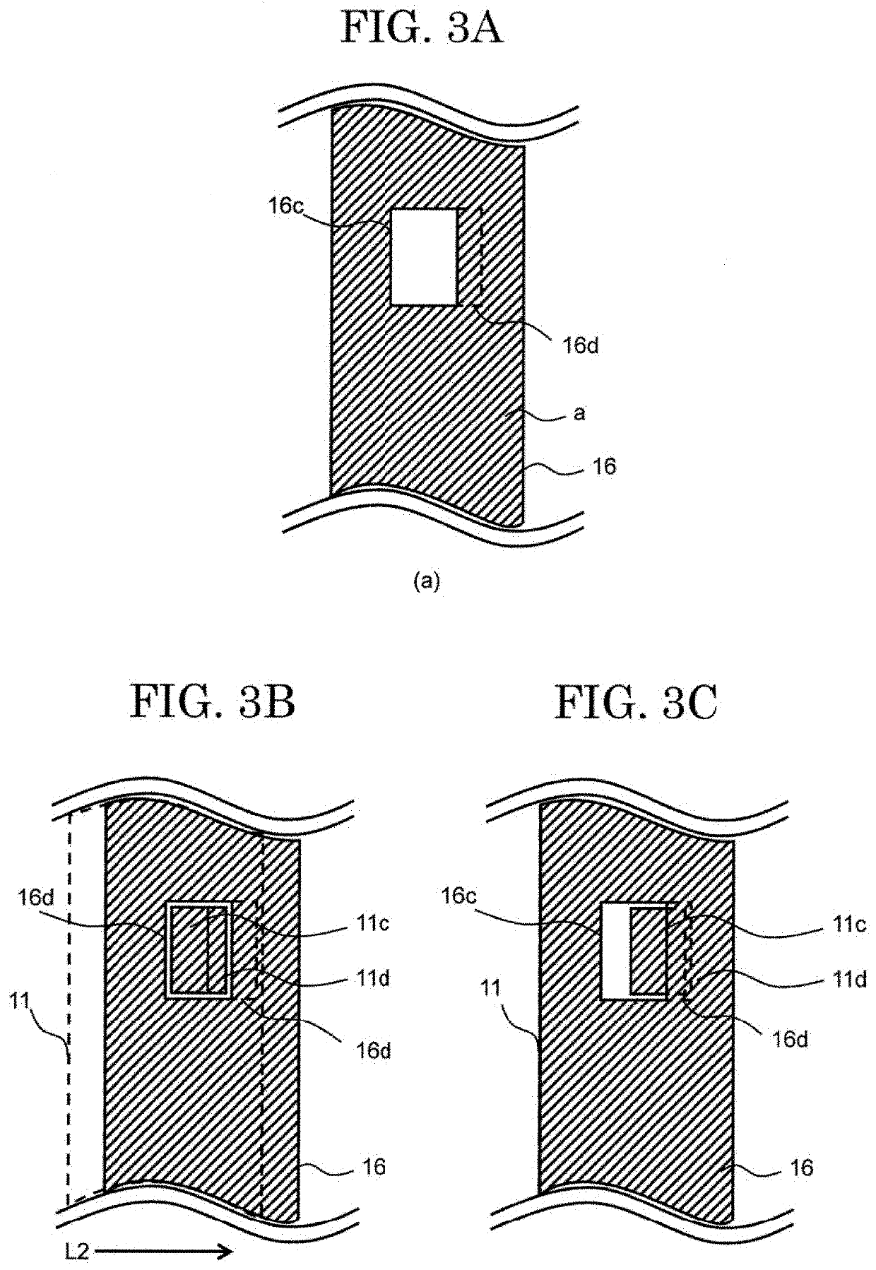
[0177]In the above-described embodiment, the first engaging portion 11b and the second engaging portion 16b are engaged by sliding the first support frame part 11 in one direction, the engagement of the first engaging portion 11b and the second engaging portion 16b is released by sliding the first support frame part 11 in the opposite direction. In this embodiment, a method of locking the first support frame part 11 by sequentially sliding the first support frame part 11 in two directions will be described.

[0178]FIGS. 14A to 14C are schematic diagrams of a support frame 111B for pellicle according to an embodiment of the present invention. FIG. 14A is a schematic diagram of the support frame 111B for pellicle viewed in the plane direction of the pattern plate where the support frame 111B for pellicle is arranged from the side where the pellicle film is arranged. FIG. 14B is a cross-sectional view of the support frame 111B for pellicle in the line segment AB of FIG. 14A, and FIG. 14C...


PUM

PropertyMeasurementUnit
wavelengthaaaaaaaaaa
heightaaaaaaaaaa
wavelengthaaaaaaaaaa

Abstract

A support frame for pellicle is provided including a first support frame part, a second support frame part, and a filter, wherein the filter has a flat plate-shaped frame shape and is sandwiched by the first support frame part and the second support frame part, the first support frame part includes a first body part having a flat plate-shaped frame shape and a first engaging portion protruded from the first body part to a thickness direction of the support frame for pellicle, and the second support frame part includes a second body part having a flat plate-shaped frame shape and a second engaging portion of the second body part engaging with the first engaging portion being arranged in a concave part provided in the thickness direction of the support frame for pellicle.

Description

CROSS REFERENCE TO RELATED APPLICATIONS[0001]This application is based upon and claims the benefit of priority from the prior Japanese Patent Application No. 2018-111648, filed on Jun. 12, 2018, and PCT Application No. PCT / JP2019 / 023267, filed on Jun. 12, 2019, the entire contents of which are incorporated herein by reference.FIELD[0002]The present invention relates to a photomask or a reticle used when manufacturing a semiconductor device or the like by a lithography technique (hereinafter referred to collectively as a “photomask”) and a pellicle or the like which is a dustproof cover for a photomask for preventing dust from adhering thereto. In particular, it relates to a support frame for pellicle for extreme ultraviolet (Extreme Ultraviolet: EUV) lithography and a pellicle, and a method for manufacturing a support frame for pellicle and, and to an exposure pattern plate and an exposure device using the pellicle.BACKGROUND[0003]A semiconductor element is manufactured through a pr...

Claims


Application Information

Patent Timeline
Patent Type & Authority Applications(United States)
IPC IPC(8): G03F1/64G03F7/20
CPCG03F1/64G03F7/70983G03F1/22
Inventor ISHIKAWA, AKIRAOKUBO, ATSUSHIONO, YOSUKEKOHMURA, KAZUO
Owner MITSUI CHEM INC
Why Eureka
Try Eureka