Monopole field electric motor-generator with switchable coil configuration

a technology of electric motors and coil configurations, applied in the direction of synchronous generators with multiple outputs, magnetic circuit rotating parts, magnetic circuit shapes/forms/construction, etc., can solve the problem that the prior art fails to teach a rotating electromagnetic machine, and achieve the effect of superior control of output parameters

Active Publication Date: 2008-03-25
CLEARWATER HLDG +1
View PDF27 Cites 21 Cited by
  • Summary
  • Abstract
  • Description
  • Claims
  • Application Information

AI Technical Summary

Benefits of technology

[0012]Another objective is to provide an electromagnetic rotating machine with superior control of its output parameters by using a novel coil switching technique and output parameter monitoring.
[0013]A further objective is to provide such a machine useful as an electric motor.
[0014]A further objective is to provide such a machine useful as an electric generator.

Problems solved by technology

However, the prior art fails to teach a rotating electromagnetic machine that provides electromagnetic fields immersed in monopole permanent magnet fields of opposite polarities as is shown in the present apparatus.

Method used


Image

  • Monopole field electric motor-generator with switchable coil configuration
  • Monopole field electric motor-generator with switchable coil configuration
  • Monopole field electric motor-generator with switchable coil configuration

Examples


Embodiment Construction

[0022]The above described drawing figures illustrate the described apparatus and its method of use in at least one of its preferred, best mode embodiments, which is further defined in detail in the following description. Those having ordinary skill in the art may be able to make alterations and modifications to what is described herein without departing from its spirit and scope. Therefore, it must be understood that what is illustrated is set forth only for the purposes of example and that it should not be taken as a limitation in the scope of the present apparatus and method of use.

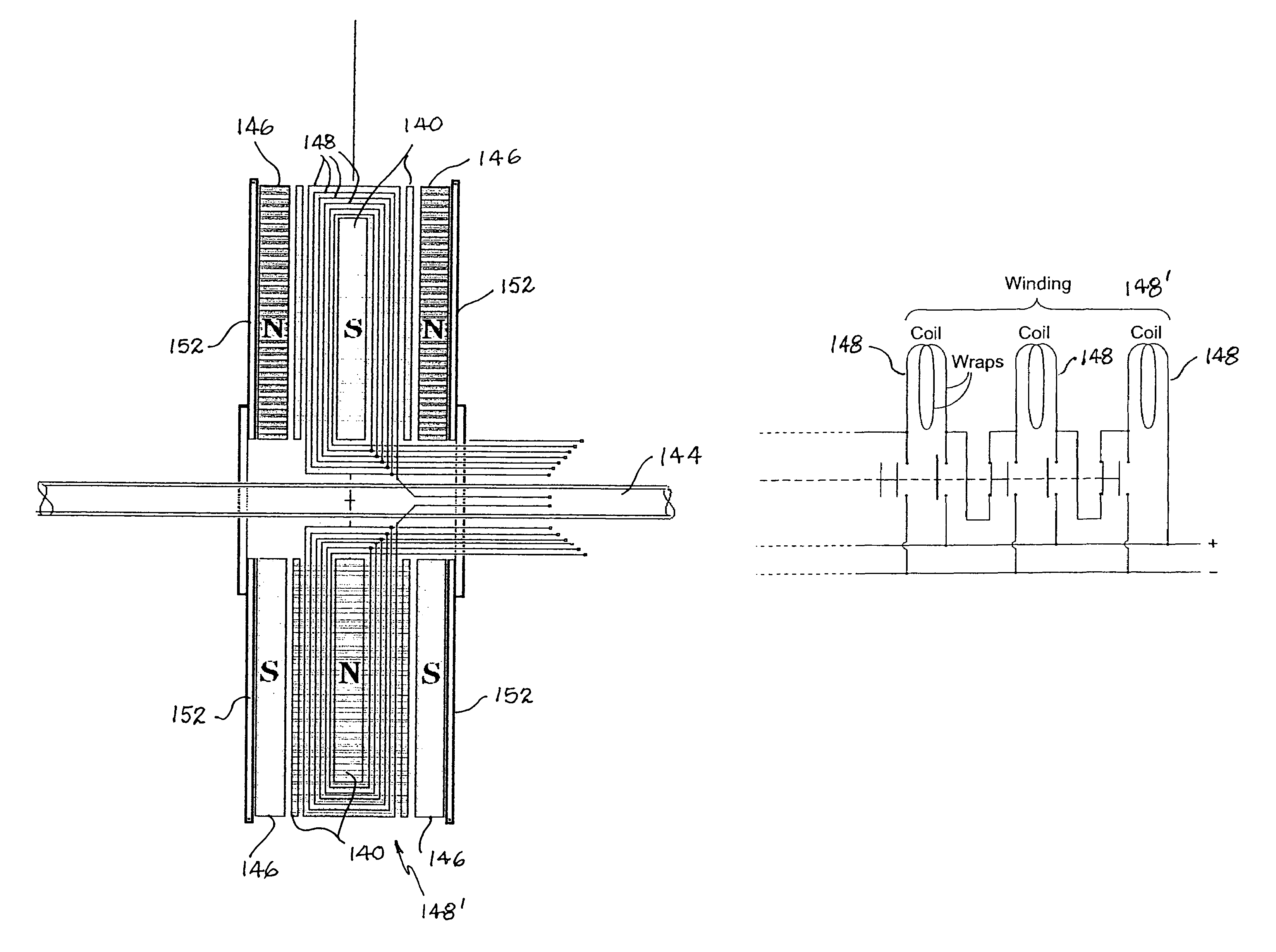
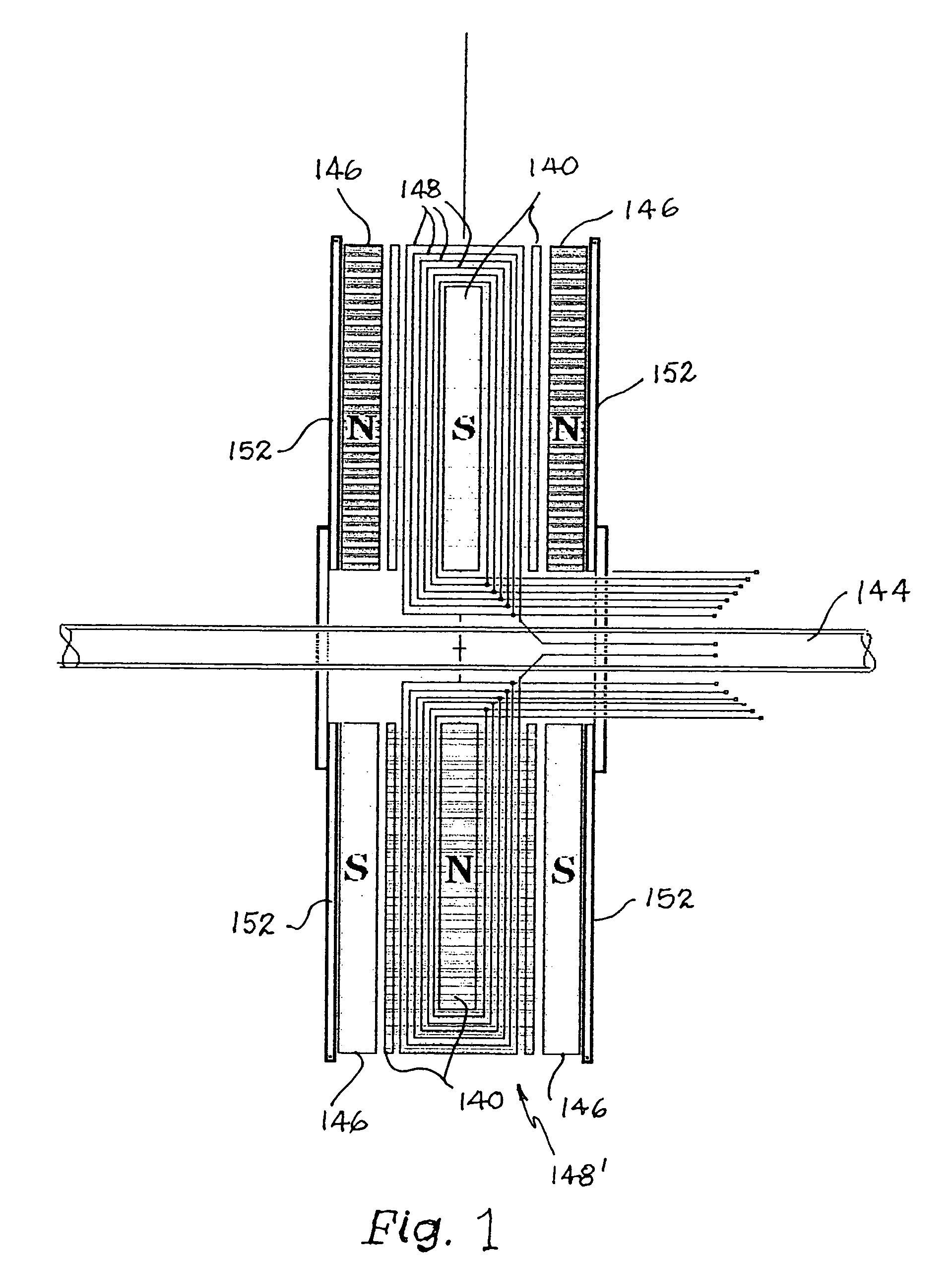
[0023]A rotating electromagnetic apparatus comprises a stator including a stator frame 152 supporting parallel spaced apart, disc-shaped permanent magnet sets, wherein each of the magnet sets comprises plural, spaced apart, co-planar magnet segments 146. The segments 146 are arranged with pairs of opposing N-N and S-S permanent magnet poles, as shown by the letters “S” for south pole and “N” for north p...


PUM


Abstract

A pair of stators produce a magnetic field within a space between them a ferromagnetic toroidal rotor is rotationally mounted within the magnetic field. A plurality of windings are wound radially on the rotor and each winding provides a plurality of coils. Each of coils is interconnected through a switch, the switch configured for placing each of the coils within each winding alternatively in one of an electrical series connection, an electrical parallel connection, and an electrically isolated connection, so that when operated as a generator, a selected output voltage and current are produced by rotor rotation and when operated as a motor a selected output speed and torque are produced.

Description

RELATED APPLICATIONS[0001]This application claims international priority from a prior filed U.S. Provisional Patent Application having U.S. Ser. No. 60 / 603,444 filed with the United States Patent Office on Aug. 20, 2004 and which is copending with this present non-provisional application. U.S. Ser. No. 60 / 603,444 is hereby incorporated herein by reference. This application is a Continuation-In-Part application of a prior filed U.S. Utility patent application having Ser. No. 11200920 and entitled Monopole Field Electric Motor Generator filed on Aug. 9, 2005.BACKGROUND[0002]1. Field of the Present Disclosure[0003]This disclosure relates generally to electric motor-generators and more particularly to such rotating electromagnetic machines having electronic switching of the rotating winding coil configuration.[0004]2. Description of Related Art[0005]The following art defines the present state of the field of the apparatus described and claimed herein:[0006]Tu et al, US 2004 / 0135452, dis...

Claims


Application Information

Patent Timeline
Patent Type & Authority Patents(United States)
IPC IPC(8): H02K21/48H02K16/04H02K19/26H02P9/00H02K21/26H02K21/24
CPCH02K3/28H02K21/24H02K21/26H02K21/48H02K23/54H02K23/64H02K1/22
Inventor BOJIUC, DUMITRU
Owner CLEARWATER HLDG
Why Eureka
Try Eureka