Device for catalytic treatment of a gas flow

a technology for catalytic treatment and gas flow, which is applied in the direction of separation processes, machines/engines, mechanical apparatus, etc., can solve the problems of power and efficiency loss, and achieve the effect of increasing efficiency and efficient use of available spa

Inactive Publication Date: 2008-04-01
VOLVO LASTVAGNAR AB
View PDF12 Cites 10 Cited by
  • Summary
  • Abstract
  • Description
  • Claims
  • Application Information

AI Technical Summary

Benefits of technology

[0009]One objective of the invention is to produce or provide a device for catalytic treatment of a gas flow which occupies a smaller volume in relation to previously known such devices, or at least has such a construction that, for a given application, it leads to more efficient use of available space. Such an application is a case in which the device is intended to be used for catalytic treatment

Problems solved by technology

A disadvantage of such devices is that the pressure pulse from one cylinder can penetrate another c

Method used


Image

  • Device for catalytic treatment of a gas flow
  • Device for catalytic treatment of a gas flow
  • Device for catalytic treatment of a gas flow

Examples


first embodiment

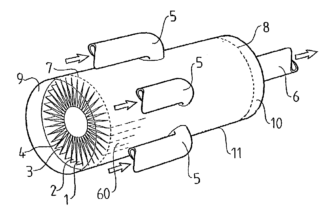
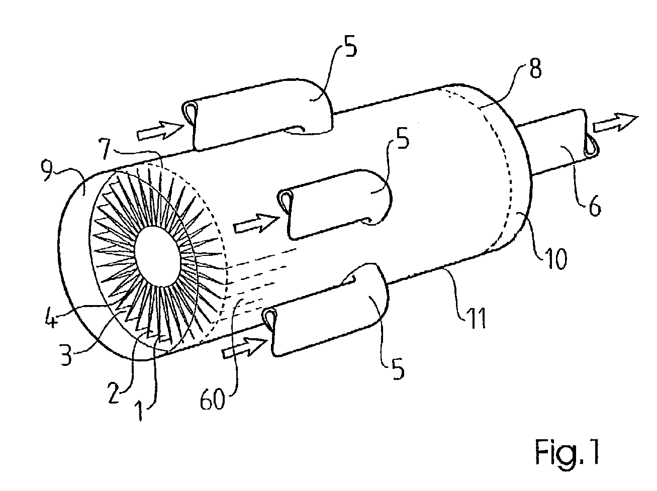
[0025]the invention as shown in FIG. 1 relates to a device (or apparatus) for catalytic oxidation of organic substances, such as hydrocarbons, in which a heat exchanger forms part of the device. In addition to the oxidation of organic substances, the device is also well suited for other combined heat exchange and catalytic treatment of gases, for example what is known as the selective reduction of nitrogen oxides with ammonia or other reducing nitrogen compounds. The device is well suited for treatment of engine exhaust gases irrespective of whether they have a high oxygen content (diesel engines) or a low oxygen content (Otto engines).

[0026]In FIG. 1, the first preferred embodiment of the invention is illustrated. In the illustrated example, the device is connected to an internal combustion engine (not shown). The device comprises a body 1 which includes a catalytic material. The body 1 is formed from a band-shaped element 2 folded into a zigzag-shaped structure (see also FIG. 3). ...

third embodiment

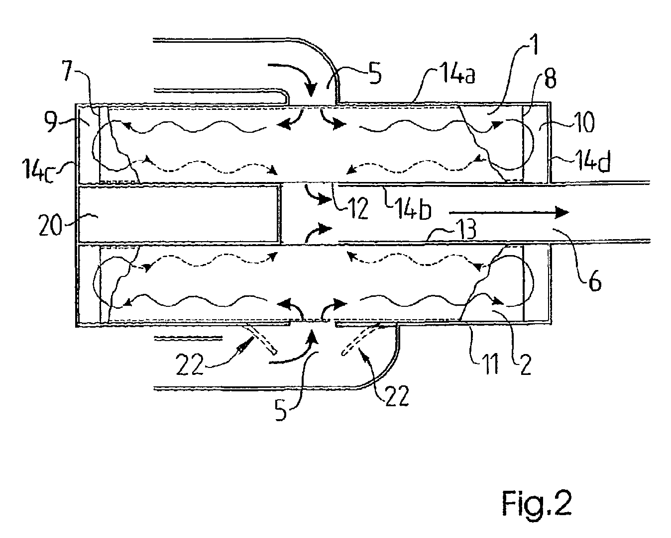
[0045]The central opening 12 illustrated in FIG. 2, which forms part of the cavity 13, is suitably replaced in the third embodiment by a number of openings that open into the cavity 13. The device is suitably provided with such an outlet opening for each inlet opening 50. The outlet opening that is connected to the left inlet opening in FIG. 7 is then arranged at a corresponding distance to the right in the figure from a central plane through the device. In a corresponding manner, the outlet opening that is connected to the right inlet opening in FIG. 7 is then arranged at a corresponding distance to the left in the figure from a central plane through the device.

[0046]The cylinders of the engine are grouped in pairs for each of the first openings 50. The groups are selected so that they originate from cylinders that do not have their exhaust valves simultaneously open.

[0047]The term gas as used herein means a gas or gas mixture, such as exhaust gases from an engine of a vehicle, whi...


PUM

PropertyMeasurementUnit
Structureaaaaaaaaaa
Lengthaaaaaaaaaa
Shapeaaaaaaaaaa

Abstract

Device for catalytic treatment of a gas flow including at least one body (1) that includes a catalytic material. The device has a number of first openings (5) for either entry of gas into or exit of gas from the catalyzer body (1), and a second opening (6) for either exit of the gas entering through the first openings or entry of gas into the catalyzer body (1) for subsequent exit through the first openings.

Description

CROSS REFERENCE TO RELATED APPLICATIONS[0001]The present application is a continuation patent application of International Application No. PCT / SE01 / 02077 filed Sep. 25, 2001 which was published in English pursuant to Article 21(2) of the Patent Cooperation Treaty and which claims priority to Swedish Patent Application No. 0003579-0 filed Oct. 4, 2000. Both applications are expressly incorporated herein by reference in their entireties.BACKGROUND OF INVENTION[0002]1. Field of the Invention[0003]The present invention relates to a device for catalytic treatment of a gas flow comprising (including, but not limited to) at least one body which includes a catalytic material. The device has a number of first openings for either entry of gas into, or exit of gas from, the catalyzer body. A second opening is provided for either the exit of the gas entering through the first openings, or entry of gas into the catalyzer body for subsequent exit through the first openings. The first openings are...

Claims


Application Information

Patent Timeline
IPC IPC(8): F01N3/28B01D53/94F01N5/02F01N3/20F01N3/24F01N13/10
CPCF01N3/2006F01N3/2046F01N3/2817F01N13/10F01N3/2889Y02T10/26F01N2240/02Y02T10/12
Inventor JOBSON, EDWARDSIMONSSON, TOMMYUDD, SOREN
Owner VOLVO LASTVAGNAR AB
Why Eureka
Try Eureka