
Method and apparatus for picking up a plastic product
a plastic product and method technology, applied in the direction of turning apparatus, food shaping, food science, etc., can solve the problem of having to move the twisted material, and achieve the effect of improving quality
- Summary
- Abstract
- Description
- Claims
- Application Information
AI Technical Summary
Benefits of technology
Problems solved by technology
Method used
Image

Examples
Embodiment Construction
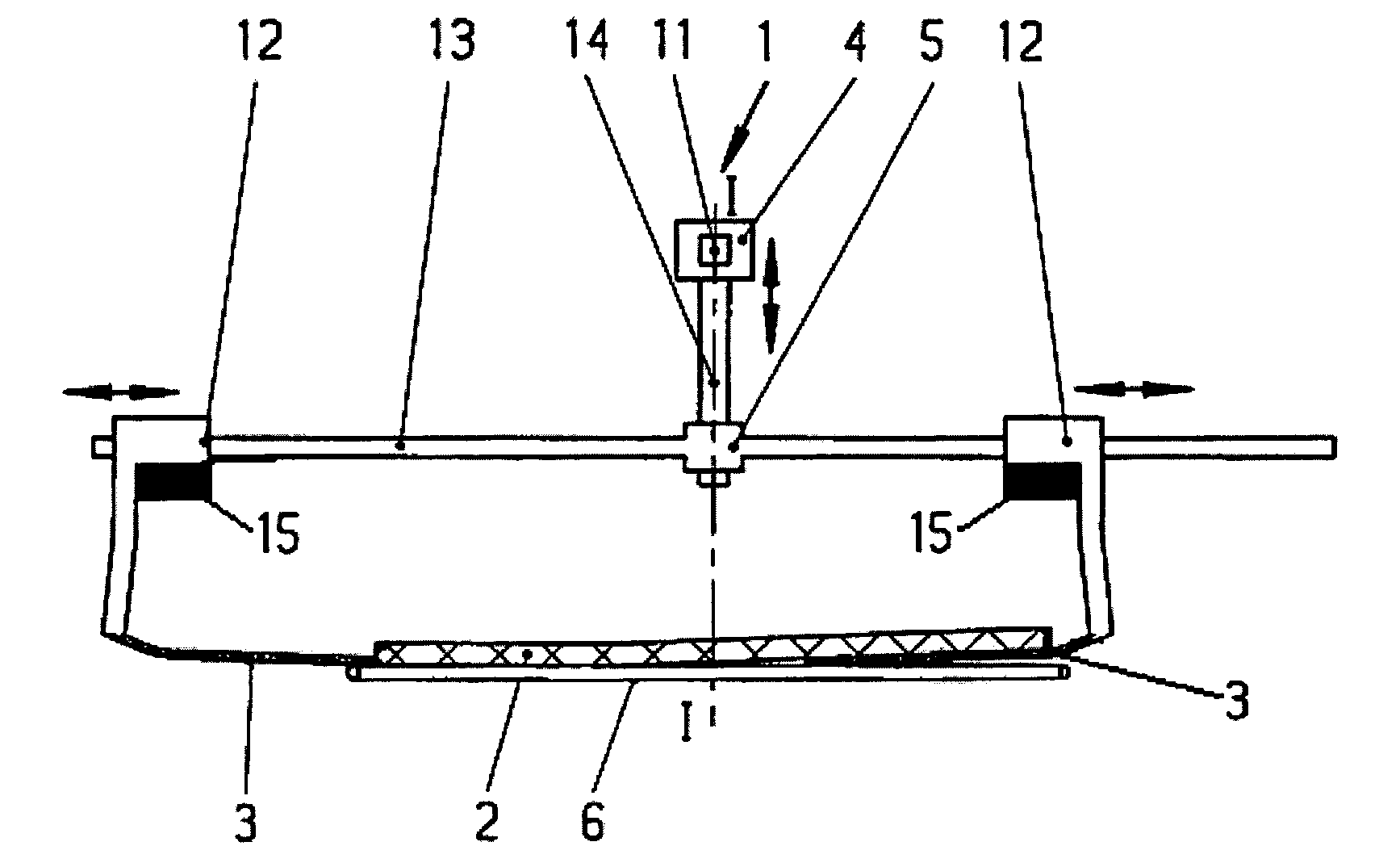
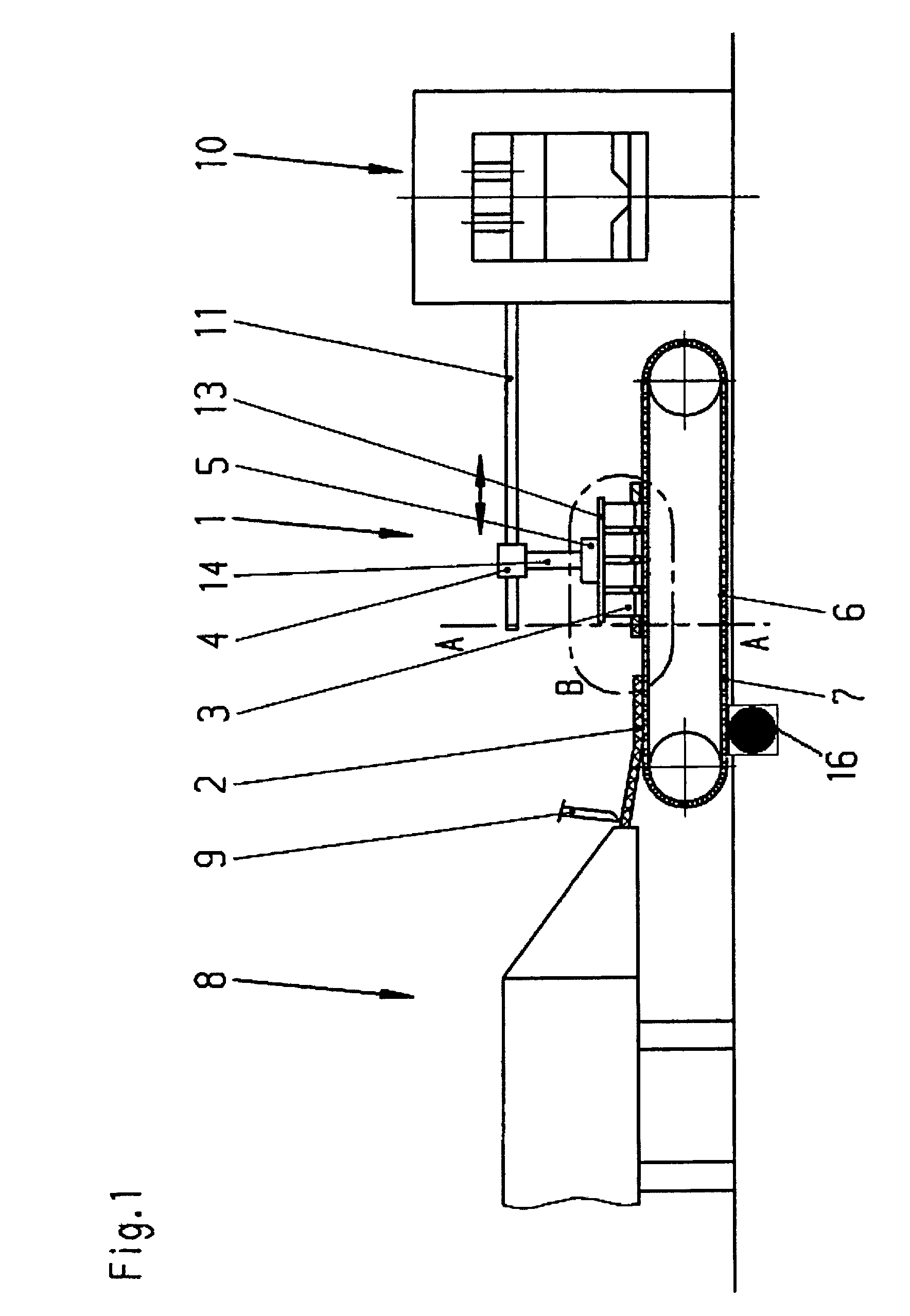
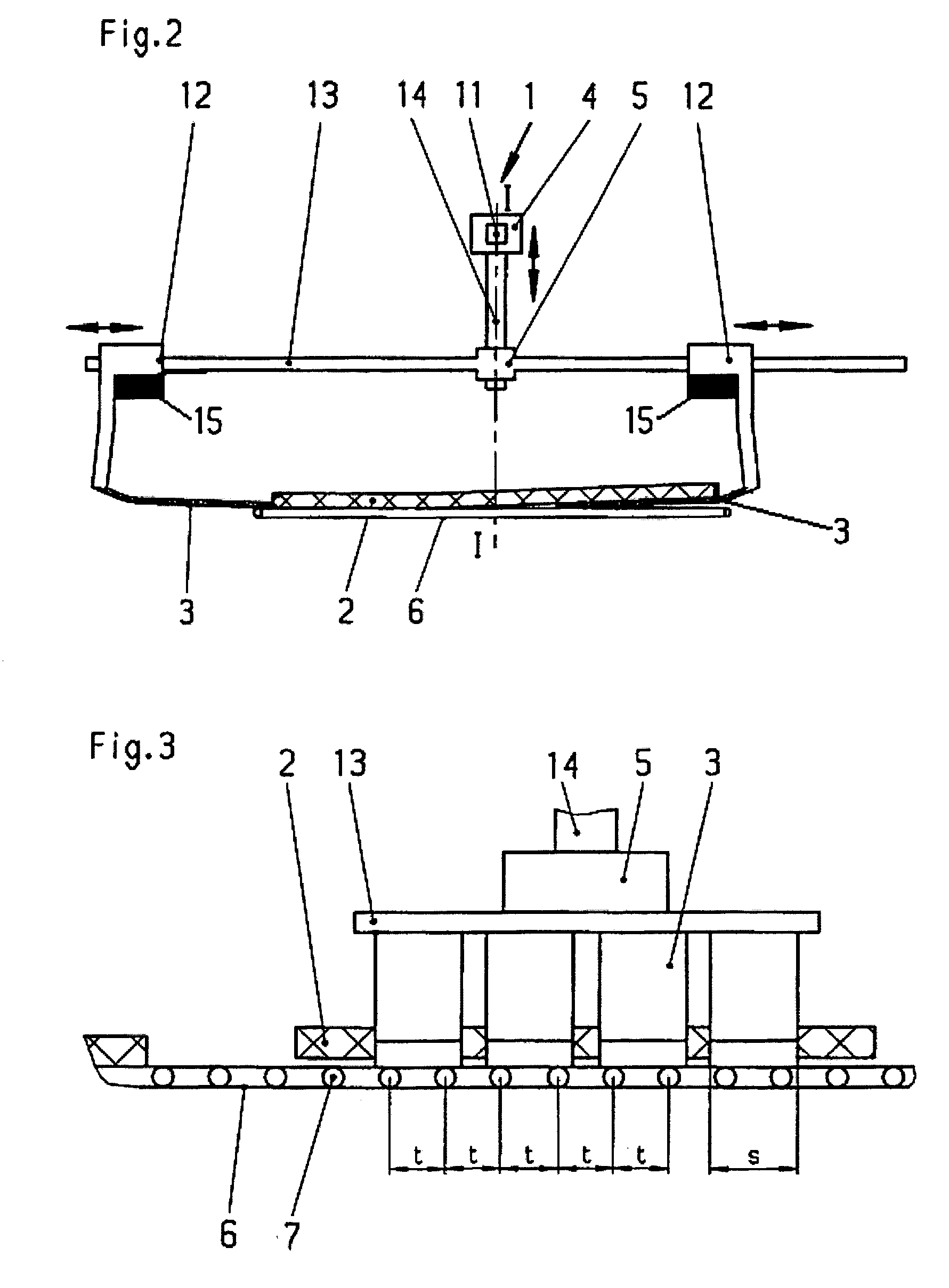
[0015]FIGS. 1 to 3 show the apparatus for the practice of the method in an imaginary system between an extruder 8 and a molding press 10. The plastic 2 comes from the extruder 8 in a strand, is divided into given lengths by a cutting mechanism 9 and laid upon the surface of an endless conveyor belt 6, in the form of a wire grating belt.
[0016]The plastic 2 is then peeled off and picked up by one or more resiliently flexible carrier plates 3 of spring steel on each longitudinal side by slipping under the two longitudinal margins of the conveyor belt 6. For that purpose the carrier plates 3 are mounted at a slight angle and can be driven by cross drives 12 across both longitudinal sides of the conveyor belt 6. The cross drives 12 are made to be moved back and forth across the longitudinal central axis I-I on the cross track 13.
[0017]As represented in FIG. 2, on the left of the longitudinal central axis I-I, the carrier plates 3 being lowered by the lift drive 5 on the lift spindle 14 s...
PUM
| Property | Measurement | Unit |
|---|---|---|
| tacky | aaaaa | aaaaa |
| viscosity | aaaaa | aaaaa |
| thickness | aaaaa | aaaaa |
Abstract
Description
Claims
Application Information