Apparatus for centrifuging a slurry

a technology of centrifuging apparatus and slurry, which is applied in the direction of centrifuges, instruments, sampled-variable control systems, etc., can solve the problems of motor failure, machine overload, and motor failure of both motors, and achieve the effect of reducing the number of motors

Inactive Publication Date: 2008-06-17
DERRICK CORP
View PDF34 Cites 65 Cited by
  • Summary
  • Abstract
  • Description
  • Claims
  • Application Information

AI Technical Summary

Benefits of technology

[0018]Another object of the invention is to provide a centrifuge system that is configured to use a customer's or operator's existing feed pump, by permitting certain specifications of the feed pump to be entered into the control computer of the centrifuge system, thereby avoiding the need for the customer to purchase an integral pump with the system.

Problems solved by technology

A danger in operating this type of centrifuge in some applications is that one or both of the motors may be presented with a load that will require the motor(s) to exceed rated torque.
This could lead to motor failure and machine overload, in some circumstances, and to system shutdown.
In some applications, such as oil well drilling, for example, down-time caused by centrifuge failure could be extremely expensive.
Both of these known solutions are unsatisfactory, however, as they both adversely affect overall system performance and / or efficiency.
A drawback of this solution, however, is that the operator had no control over the predetermined torque limits and, under some operating conditions, the operator might want to run the motors within different limits.
Another problem in existing centrifuge systems is that some users / operators have existing pump / gear box assemblies that they would like to use with a newly installed centrifuge.
Heretofore, this was not possible, because the computer controlled centrifuges were not programmed to run with third party (i.e., other than OEM) pumps.

Method used


Image

  • Apparatus for centrifuging a slurry
  • Apparatus for centrifuging a slurry
  • Apparatus for centrifuging a slurry

Examples


Embodiment Construction

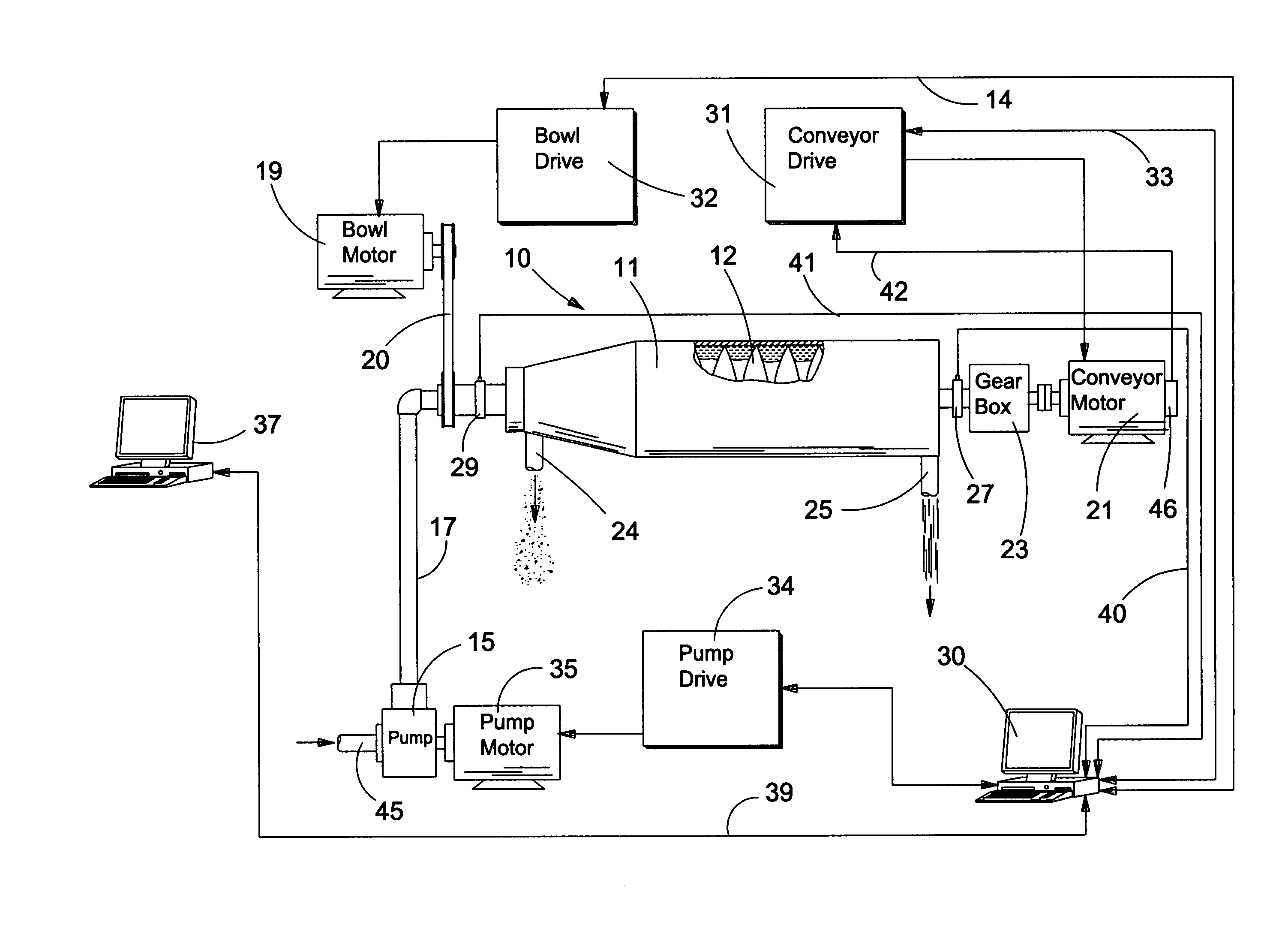
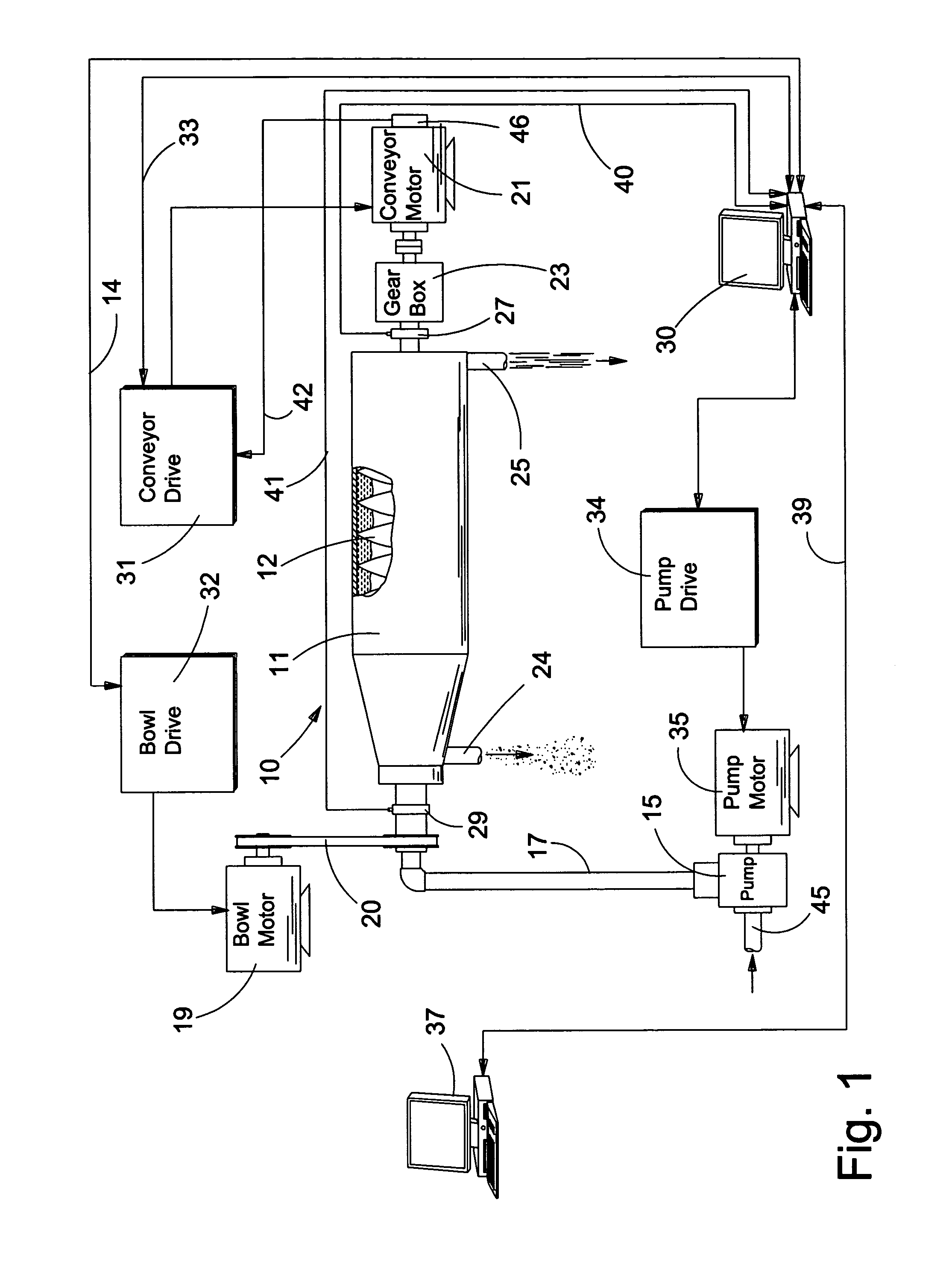
[0025]It should be appreciated at the outset that the method and apparatus of centrifuging of the invention is suitable for use in a variety of applications—virtually any application that requires a centrifuge. In a preferred embodiment of the invention, the patentee tested the invention in an earth drilling application. Thus, while the description herein describes the invention in this particular application, it should be appreciated that the appended claims are not intended to be so limited. In addition, it should be appreciated that the centrifuge of the present invention is adaptable for use in either closed or open systems.

[0026]In reading this patent, it should be appreciated that like reference numbers on different drawing views represent identical structural elements of the invention. It should also be appreciated that the centrifuge of the present invention is ultimately controlled by a general purpose industrial hardened computer specially programmed to control the bowl dr...


PUM


Abstract

A method and apparatus for centrifuging. The apparatus comprises a centrifuge for centrifuging a slurry, comprising a bowl driven by a bowl drive motor, a screw conveyor driven by a screw conveyor drive motor, a pump driven by a pump motor, a bowl drive unit operatively arranged to drive the bowl drive motor, a conveyor drive unit operatively arranged to drive the screw conveyor drive motor, a pump drive unit operatively arranged to drive the pump drive motor, and, a general purpose first computer specially programmed to control the bowl drive unit to drive the bowl drive motor at a first constant speed and to control the screw conveyor drive unit to drive the screw conveyor drive motor at a second constant speed and to monitor the torques of the bowl drive motor and the screw conveyor drive motor, while simultaneously controlling the pump drive unit to variably control flow of the slurry through the centrifuge so as to drive one of the bowl drive motor or the screw conveyor motor at a pre-set operating torque.

Description

RELATED APPLICATION[0001]This is a continuation patent application under 35 USC 120 which claims the benefit of U.S. patent application Ser. No. 10 / 138,202, filed May 3, 2002, entitled, “APPARATUS FOR CENTRIFUGING A SLURRY.” U.S. patent application Ser. No. 10 / 138,202 is a continuation-in-part patent application under 35 USC 120 which claims the benefit of U.S. patent application Ser. No. 10 / 133,889, filed Apr. 26, 2002, entitled, “APPARATUS FOR CENTRIFUGING A SLURRY.” U.S. patent application Ser. No. 10 / 133,889 and U.S. patent application Ser. No. 10 / 138,202 are incorporated by reference herein. U.S. patent application Ser. No. 10 / 133,889 issued as U.S. Pat. No. 6,905,452, on Jun. 14, 2005. U.S. patent application Ser. No. 10 / 138,202 issued as U.S. Pat. No. 6,971,982, on Dec. 6, 2005.REFERENCE TO COMPUTER PROGRAM LISTING APPENDIX[0002]This patent includes a computer program listing appendix on compact disc. Two duplicate compact discs are provided herewith. Each compact disc contai...

Claims


Application Information

Patent Timeline
Patent Type & Authority Patents(United States)
IPC IPC(8): B04B13/00B04B1/20
CPCB04B1/2016B04B11/02B04B13/00
Inventor KIRSCH, RAYMOND
Owner DERRICK CORP
Why Eureka
Try Eureka