Cell phone antenna switching circuit and antenna switching method

a technology of antenna switching circuit and cell phone antenna, which is applied in the direction of diversity/multi-antenna system, independent non-interfering antenna combination, spatial transmit diversity, etc., can solve the problems of antenna characteristics deterioration, unfavorable antenna selection, and deterioration of reception characteristics, so as to achieve good reception characteristics

Inactive Publication Date: 2008-06-24
NEC CORP
View PDF17 Cites 8 Cited by
  • Summary
  • Abstract
  • Description
  • Claims
  • Application Information

AI Technical Summary

Benefits of technology

[0013]It is an object of the present invention to provide a cell phone antenna switching circuit and antenna switching method which obtain good reception characteristics by automatically switching built-in antennas even when a built-in antenna in a cell phone comes close to the human body during speech communication, and select an optimal antenna during continuous transmission / reception in speech communication or packet communication after an antenna is selected in a cell phone designed to perform continuous transmission / reception as in the CDMA scheme or the like.

Problems solved by technology

The cell phone is placed near the user during speech communication, and hence the influence of the human body on an antenna is a factor that causes a deterioration in reception characteristics and the like.
If an antenna is placed at a portion where the movement of the hand exerts influences, an unfavorable antenna may be erroneously selected during key operation due to unstable reception electric field levels during the key operation.
In addition, since the cell phone comes into contact with part of the human body during speech communication, the antenna characteristics deteriorate.
If an antenna is placed in a portion where the movement of the hand exerts influences, in particular, since the reception electric field levels become unstable during key operation, an unfavorable antenna may be erroneously selected during the key operation.

Method used


Image

  • Cell phone antenna switching circuit and antenna switching method
  • Cell phone antenna switching circuit and antenna switching method
  • Cell phone antenna switching circuit and antenna switching method

Examples


Embodiment Construction

[0018]An embodiment of the present invention will be described next with reference to the accompanying drawings.

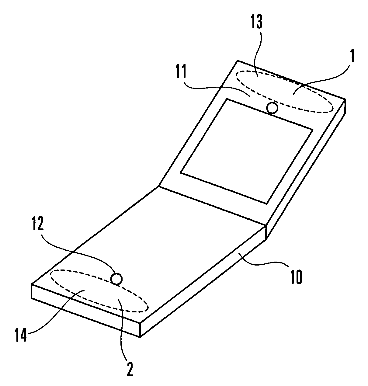
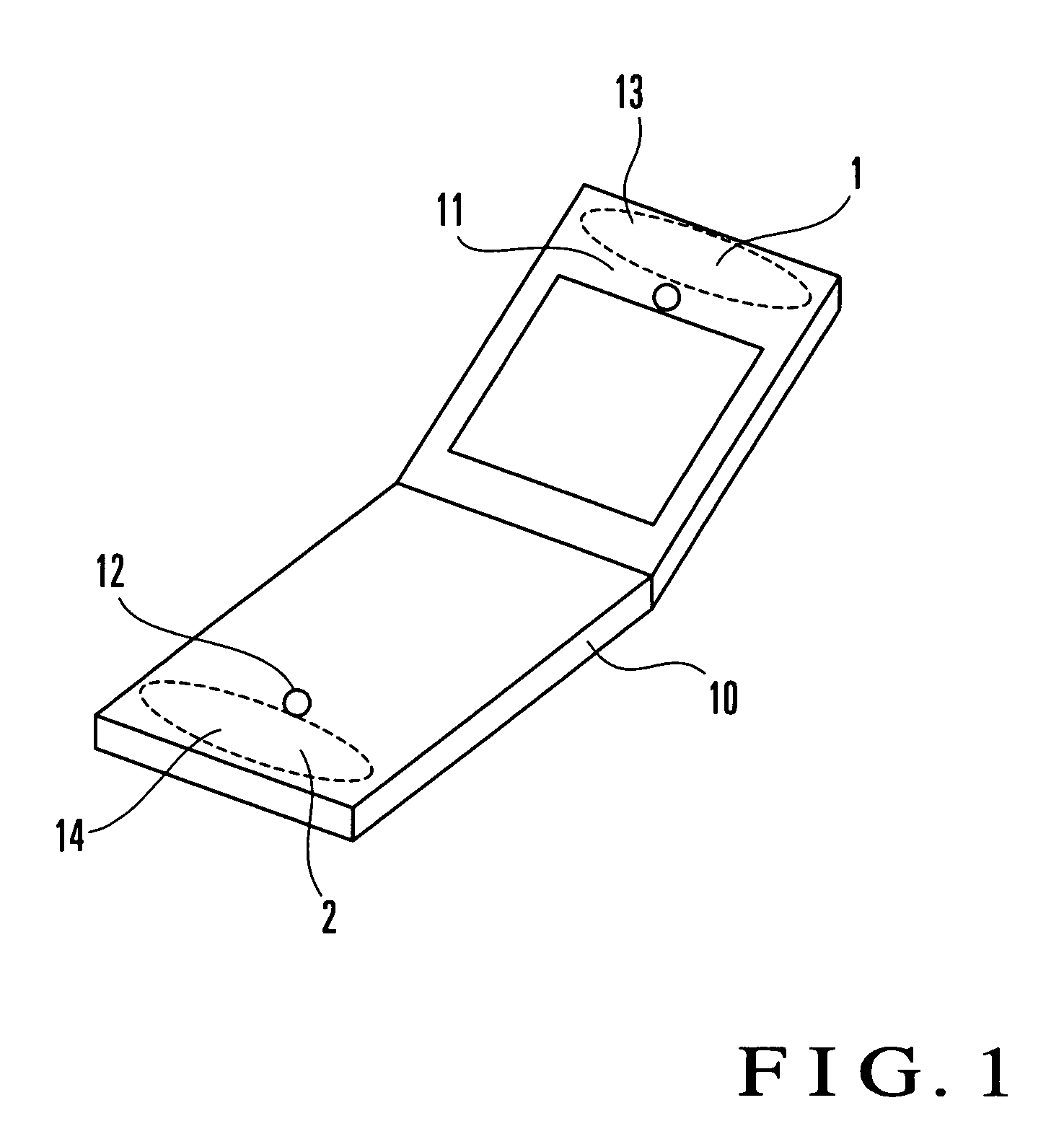
[0019]FIG. 1 shows a cell phone antenna switching circuit according to an embodiment of the present invention.

[0020]This embodiment shown in FIG. 1 is comprised of a speaker 11 and microphone 12 incorporated in a cell phone 10, an antenna 1 mounted in an area 13, and an antenna 2 mounted in an area 14.

[0021]FIG. 1 shows the positions of the two built-in antennas of the cell phone of the present invention. In this case, the shape and material of each antenna are irrelevant to the present invention. The speaker 11 and microphone 12 of the cell phone are described to mark the places where the two built-in antennas are mounted. However, the functions of these components are irrelevant to the present invention but they serve as only marks in explaining the positions of the antennas. In this case, the two built-in antennas will be referred to as the antenna 1, which is located o...


PUM


Abstract

A cell phone antenna switching circuit includes a plurality of built-in antennas which perform radio transmission/reception. This circuit includes reception level measuring sections and an antenna switching section. The reception level measuring sections measure the reception levels of the corresponding built-in antennas. The antenna switching section always automatically selects an antenna whose reception level is high during a standby period, and selects an antenna with good antenna characteristics depending on a function during speech communication. A cell phone antenna switching method is also disclosed.

Description

BACKGROUND OF THE INVENTION[0001]The present invention relates to a cell phone antenna switching circuit and antenna switching method and, more particularly, to a cell phone antenna switching circuit and switching method which use two built-in antennas in a cell phone which requires continuous transmission / reception as in the CDMA (Code Division Multiple Access) scheme or the like and selectively use the antennas depending on the function of the cell phone which is to be used.[0002]In general, with increasing reductions in the size and thickness of a cell phone, it has excellent portability. The cell phone is placed near the user during speech communication, and hence the influence of the human body on an antenna is a factor that causes a deterioration in reception characteristics and the like.[0003]Of the recent cell phones, cell phones capable of continuous transmission / reception as in the CDMA (Code Division Multiple Access) scheme or the like which realizes good communication qu...

Claims


Application Information

Patent Timeline
Patent Type & Authority Patents(United States)
IPC IPC(8): H04B1/06H04B1/44H01Q1/24H01Q3/24H01Q21/28H04B7/06H04B7/08H04B7/26H04M1/00H04M1/02H04M1/725
CPCH01Q1/243H01Q3/24H01Q21/28H04B7/0808
Inventor SUNAGA, TERUHIDE
Owner NEC CORP
Why Eureka
Try Eureka