
Digital data transmitting device and digital data receiving device

A technology of sending device and receiving device, which is applied in the direction of digital transmission system, modulated carrier system, transmission system, etc. It can solve the problems of inability to detect phase error, inability to perform stable decoding, and inability to perform synchronous detection, etc., to achieve improved reception characteristics Effect

Active Publication Date: 2010-03-03
NIPPON HOSO KYOKAI
View PDF2 Cites 7 Cited by
  • Summary
  • Abstract
  • Description
  • Claims
  • Application Information

AI Technical Summary

Problems solved by technology

[0028] However, when the characteristics of the transmission path change due to changes in the satellite repeater (satellite repeater) over time or changes in the amount of back off, it is impossible to detect the optimum phase error, so there is a possibility that stabilization cannot be performed. The problem of synchronous detection of
In addition, when the characteristics of the transmission path change, there is also the problem that stable decoding cannot be performed and the carrier to noise ratio (C / N, carrier to noise ratio) cannot be effectively reduced.

Method used


Image

  • Digital data transmitting device and digital data receiving device
  • Digital data transmitting device and digital data receiving device
  • Digital data transmitting device and digital data receiving device

Examples


Embodiment Construction

[0063] Hereinafter, specific embodiments will be described in detail using the drawings.

[0064] [sending device]

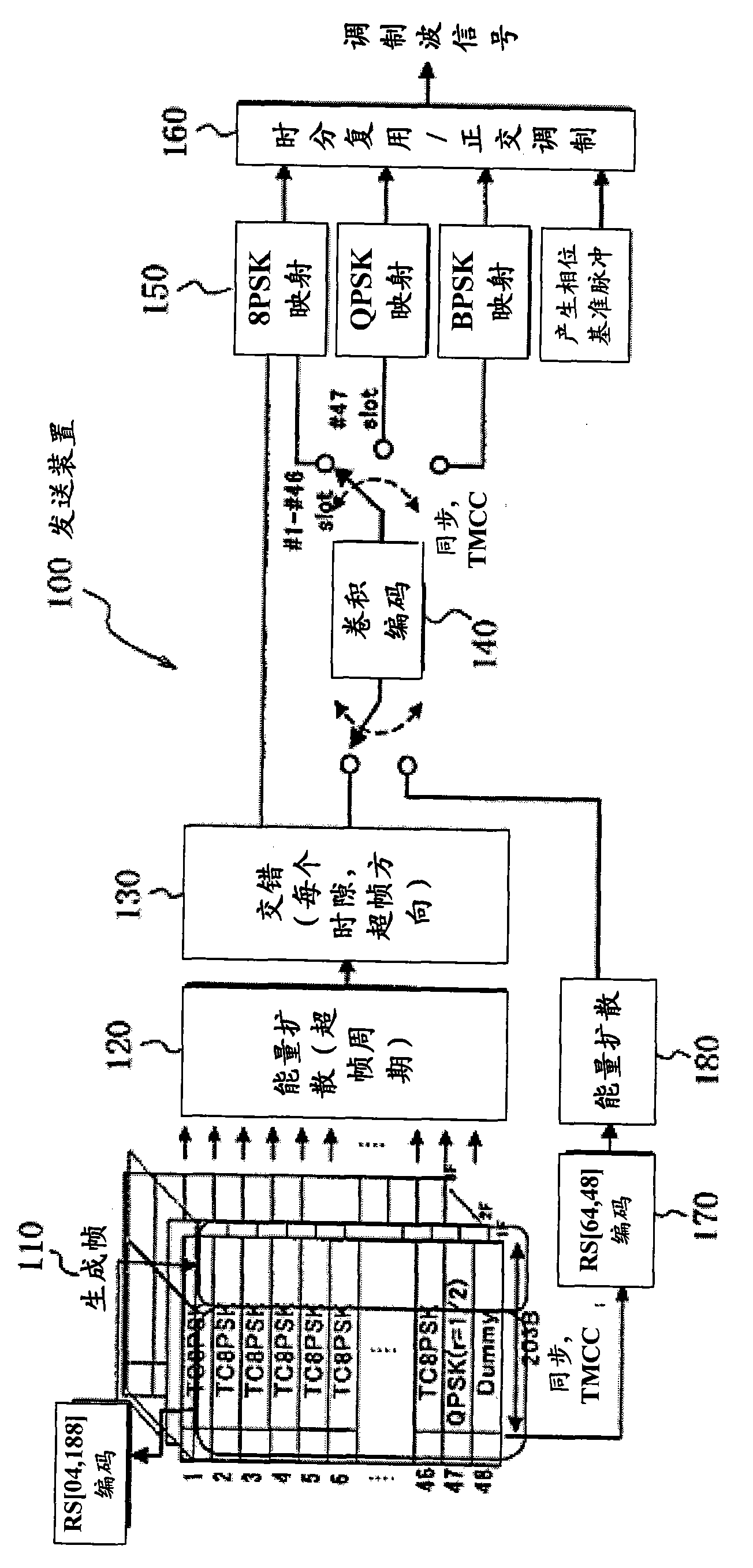
[0065] First, a transmission device according to an embodiment of the present invention will be described. Figure 8 It is a diagram showing the configuration of a transmission device according to an embodiment of the present invention. The transmitting apparatus 1 transmits, as a pilot signal, symbols allocated to all signal points in a predetermined order for each modulation scheme. Thereby, the receiving apparatus can know the signal point corresponding to each symbol, and the reception characteristic can be improved by using the signal point. Among them, when the signal point is configured as Figure 12 When there are multiple signal points on concentric circles like the signal point configuration shown, the amplitude and phase of each signal point on the concentric circles are affected equally by the nonlinear characteristics of the transmission line, so...


PUM


Abstract

A digital data transmitting device and a digital data receiving device are provided for making it possible to follow changes in transmission line characteristic, if any, due to aging of a repeater, etc., so that a receiving characteristic can be improved. A transmitting device (1) generates multiple frames that are comprised of N slots for control information, data, an outer code parity, a stuff bit, and an internal code parity and to which a synchronous signal, a pilot and transmission control signal, and a parity are added; and transmits data in each slot with a transmission system designated by the transmission control signal. In this case, the pilot signal is symbols allocated to all signal points in an order determined in advance for every modulation system. A receiving device (2) rewrites a phase error table (214) with the pilot signal to seek a phase error and carries out a synchronous detection. Further, the receiving device rewrites a likelihood table (235) and carries out the decoding of the internal code. With this, reception processing suitable for distortions of a transmission line characteristic can be carried out, so that the receiving characteristic can be improved.

Description

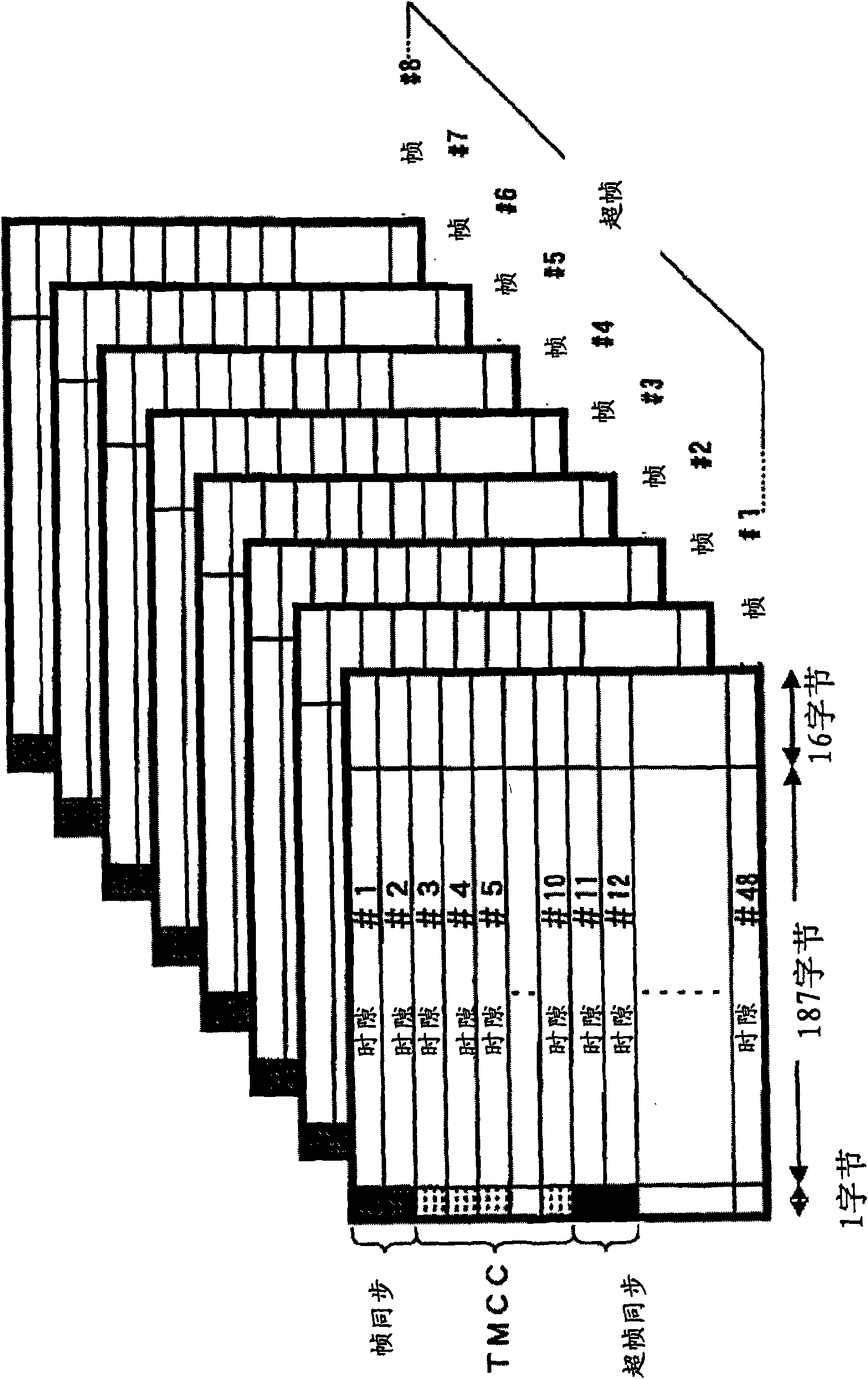
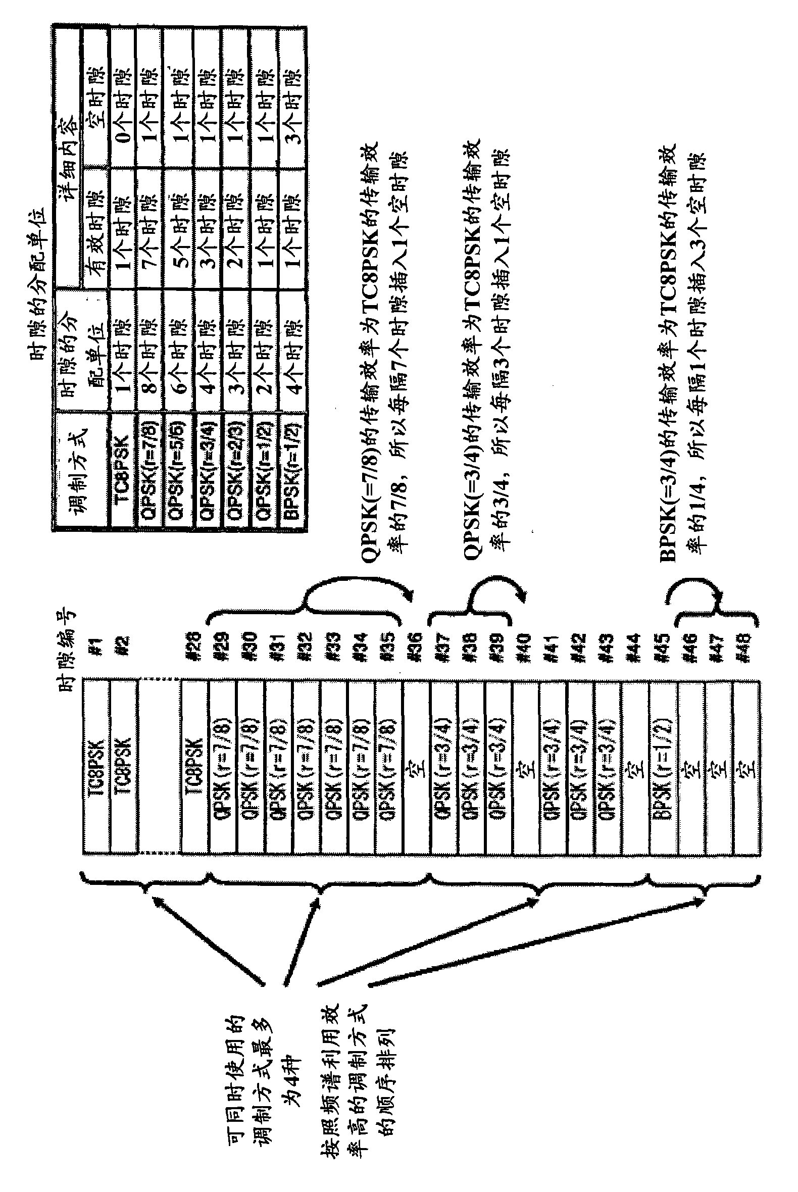
technical field [0001] The present invention relates to a transmission technology of digital data, in particular to a transmission device forming a frame structure for data transmission and a receiving device for recognizing the frame structure and receiving data . Background technique [0002] First, a transmission method of broadcasting satellite digital broadcasting (Broadcasting Satellite Digital Broadcasting) will be described. figure 1 It is a diagram showing the configuration of a multi-frame in BS digital broadcasting. figure 1 In the multiframe of BS digital broadcasting, a superframe (superframe) of one channel (channel) is constituted by eight frames #1 to #8. Frames #1 to #8 are composed of 48 slots (slots) #1 to #48, respectively. Here, a "slot" is a time slot in which a packet (188 bytes) of a Moving Picture Experts Group (MPEG)-2 transport stream (Transport Stream, TS) can be removed from the leading edge. The area on the memory (memory) where the part oth...

Claims


Application Information

Patent Timeline
Patent Type & Authority Applications(China)
IPC IPC(8): H04L27/38
CPCH04L2027/0024H04L1/0045H04L27/38H04L2027/0067H04L1/0071H04L5/0048H04L27/2657H04L27/34
Inventor 桥本明记铃木阳一正源和义田中祥次筋诫久
Owner NIPPON HOSO KYOKAI
Learn More