Digital radio communication system

A communication system, digital wireless technology, applied in the direction of digital transmission system, transmission system, baseband system, etc., can solve problems such as difficult calculation of receiving signal points, deterioration of receiving characteristics, etc.

Inactive Publication Date: 2003-12-10
PANASONIC CORP
View PDF4 Cites 7 Cited by
  • Summary
  • Abstract
  • Description
  • Claims
  • Application Information

AI Technical Summary

Problems solved by technology

[0003] However, one problem with M-ary modulation is that the more bits are arranged in a symbol, the smaller the signal point spacing in the signal space diagram, making it difficult to determine the received signal point and calculate the likelihood , and lead to deterioration of reception characteristics

Method used


Image

  • Digital radio communication system
  • Digital radio communication system
  • Digital radio communication system

Examples


Embodiment 1

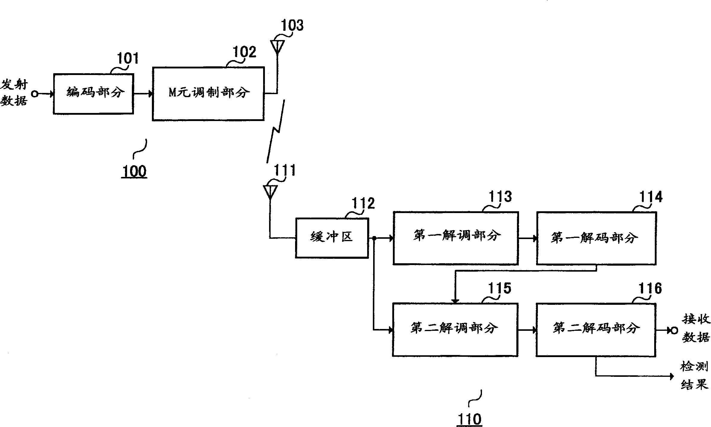
[0098] figure 1 is a structural block diagram of a wireless communication system according to Embodiment 1 of the present invention. exist figure 1 In the shown wireless communication system, wireless communication is performed between the transmitting device 100 and the receiving device 110 . Unless otherwise specified, in the following embodiments, the implementation of 8PSK is taken as an example for description.

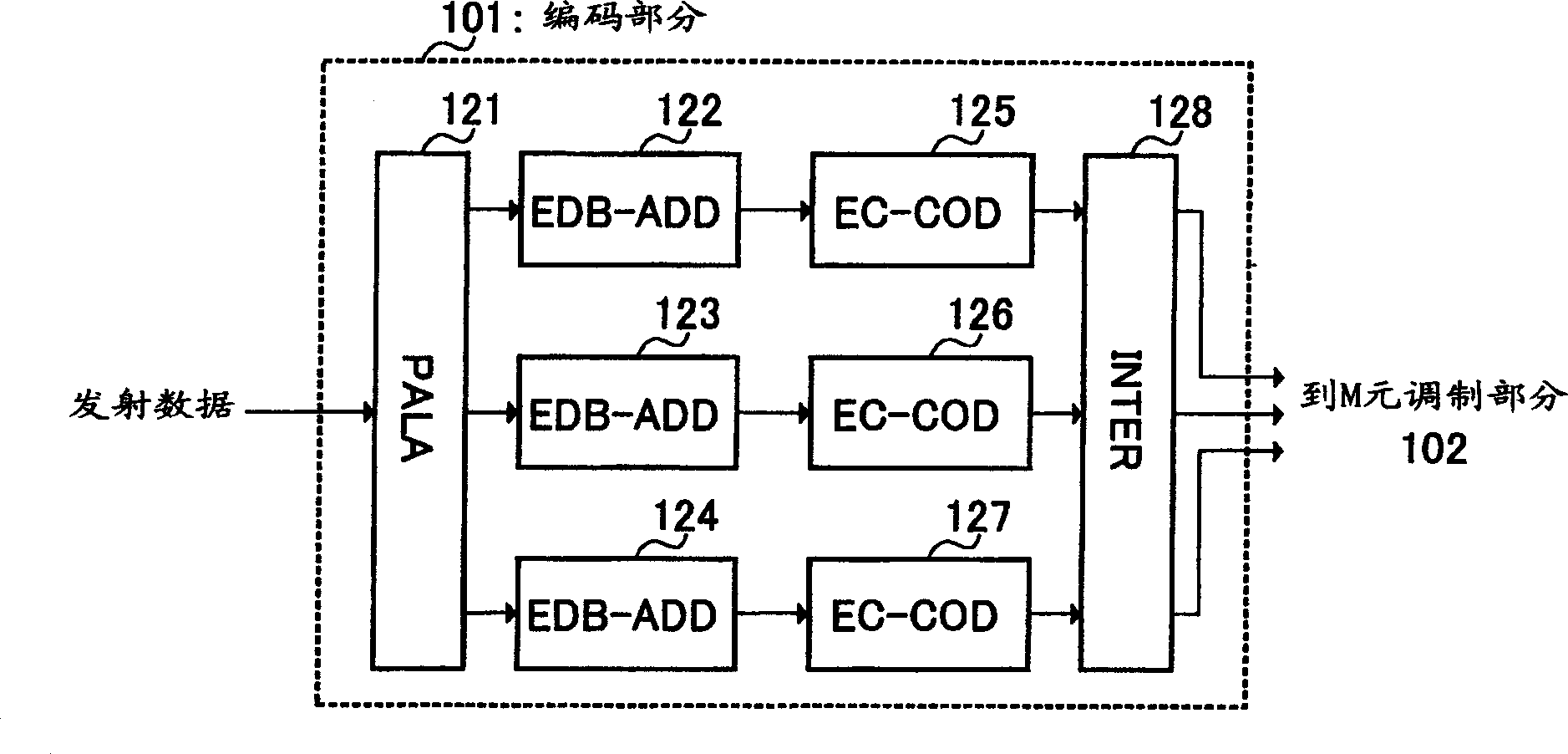
[0099] In the transmission device 100, the encoding section 101 performs error detection encoding of transmission data for each predetermined error detection unit, and performs error correction encoding for each predetermined error correction unit. M-ary modulation section 102 performs M-ary modulation on the output signal from encoding section 101 , and performs wireless transmission of the signal through antenna 103 .

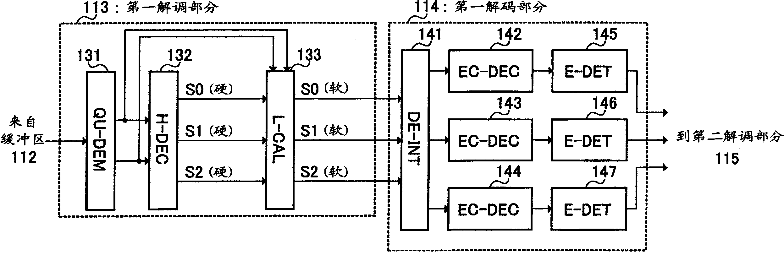
[0100] In receiving device 110, a signal received from antenna 111 is first stored into buffer 112, and then output to first demodulation se...

Embodiment 2

[0127] Embodiment 2 of the present invention is a modification of Embodiment 1, and describes the case where a plurality of error detection units are combined as one error correction unit.

[0128] FIG. 6 is a block diagram showing the structure of a wireless communication system according to Embodiment 2 of the present invention. In the wireless communication system shown in FIG. 6 , wireless communication is performed between the transmitting device 200 and the receiving device 210 . In the transmitting device 200, the structure of the coding part 201 is different from figure 1 The encoding part 101 shown, and in the receiving device 210, the first decoding part 214 and the second decoding part 216 are different from figure 1 A first decoding section 114 and a second decoding section 116 are shown.

[0129] Figure 7 is a block diagram of the internal structure of the encoding section 201 of the transmitting device 200 shown in FIG. 6 . Figure 7 neutralize figure 2 Th...

Embodiment 3

[0136] Embodiment 3 of the present invention is a modification of Embodiment 1, and describes the case by providing error detection units different according to bit positions, and performing interleaving for each error detection unit so that the The number of independent error detection units is the same as the number of bits arranged in one symbol.

[0137] Figure 10 is a structural block diagram of a wireless communication system according to Embodiment 3 of the present invention. exist Figure 10 In the shown wireless communication system, wireless communication is performed between a transmitting device 300 and a receiving device 310 . In the transmitting device 300, the structure of the encoding part 301 is different from figure 1 The encoding part 101 shown, and in the receiving device 310, the first decoding part 314 and the second decoding part 316 are different from figure 1 A first decoding section 114 and a second decoding section 116 are shown.

[0138] Fig...


PUM


Abstract

An encoding section (101) subjects an each predetermined error-detection unit of data to error-detection encoding. A multinary modulation section (102) disposes coded data included in error-detection units in one transmission unit and transmits the transmission unit. A first decoding section (114) decodes the received signal and detects an error, if any, in the decoded signal for each error-detection unit. A second decoding section (115) changes the likelihood of each bit on the basis of the result of the error detection by the first decoding section (114). Thus the ability of error correction of a signal multinary-modulated by using the high-accuracy likelihood is improved, thereby improving the transmission quality.

Description

technical field [0001] The present invention relates to a digital wireless communication system using M-ary modulation, in particular to a digital wireless communication system capable of improving demodulation characteristics of signals modulated by M-ary modulation. Background technique [0002] With the recent diversification of services, there has been a demand to transmit a larger amount of data in the downlink. To meet this requirement, M-ary modulation is used, in which multiple bits are arranged in one symbol. M-ary modulation is a modulation method for arranging multiple bits in one symbol. Well-known M-ary modulation methods include: QPSK, in which 2 bits are arranged in one symbol; 8PSK, in which 3 bits are arranged in one symbol; and 16QAM, in which 4 bits are arranged in one symbol. [0003] However, one problem with M-ary modulation is that the more bits are arranged in a symbol, the smaller the signal point spacing in the signal space diagram, making it diff...

Claims


Application Information

Patent Timeline
Patent Type & Authority Applications(China)
IPC IPC(8): H04L27/18H04L1/00H04L27/22H04L27/34H04L27/38
CPCH04L1/007H04L1/0058H04L27/3405H04L27/22H04L1/1635H04L1/0041H04L1/005H04L1/1893H04L1/0071H04L25/067H04L1/0061H04L27/38H04B1/40H04L1/00
Inventor 上杉充三好宪一
Owner PANASONIC CORP
Why Eureka
Try Eureka