Control channel transmission method and radio communication apparatus

A wireless communication device and control channel technology, applied in the transmission system, digital transmission system, multiplex communication, etc., can solve the problems of unsatisfactory signal orthogonality, decline of receiving characteristics, increase of peak-to-average power ratio, etc.

Inactive Publication Date: 2009-12-16
FUJITSU LTD
View PDF0 Cites 7 Cited by
  • Summary
  • Abstract
  • Description
  • Claims
  • Application Information

AI Technical Summary

Problems solved by technology

This means that multi-carrier transmission is performed, but unlike single-carrier transmission in which only transmission data and pilot signals are multiplexed on the time axis (see Figure 7A and Figure 7B ), PAPR (Peak-to-Average Power Ratio) increased
[0010] On the other hand, based on Figure 9A and Figure 9B In the case of transmission by the MIMO method shown in , the increase in PAPR can be prevented and the throughput can be improved, but the signals between the transmitting antennas 17-1 and 17-2 are not ideally orthogonal to each other, so the reception characteristics are degraded

Method used


Image

  • Control channel transmission method and radio communication apparatus
  • Control channel transmission method and radio communication apparatus
  • Control channel transmission method and radio communication apparatus

Examples


Embodiment Construction

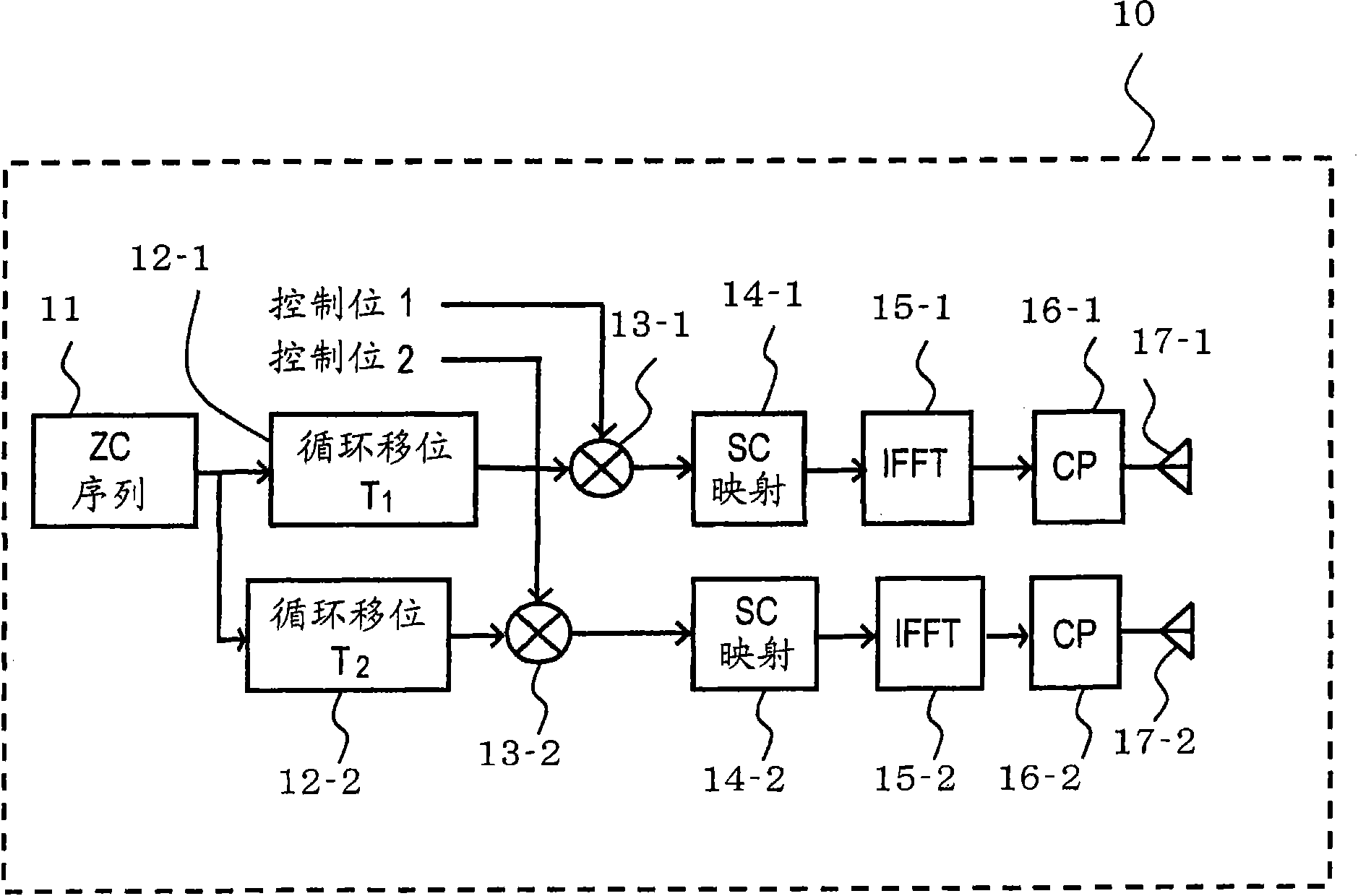
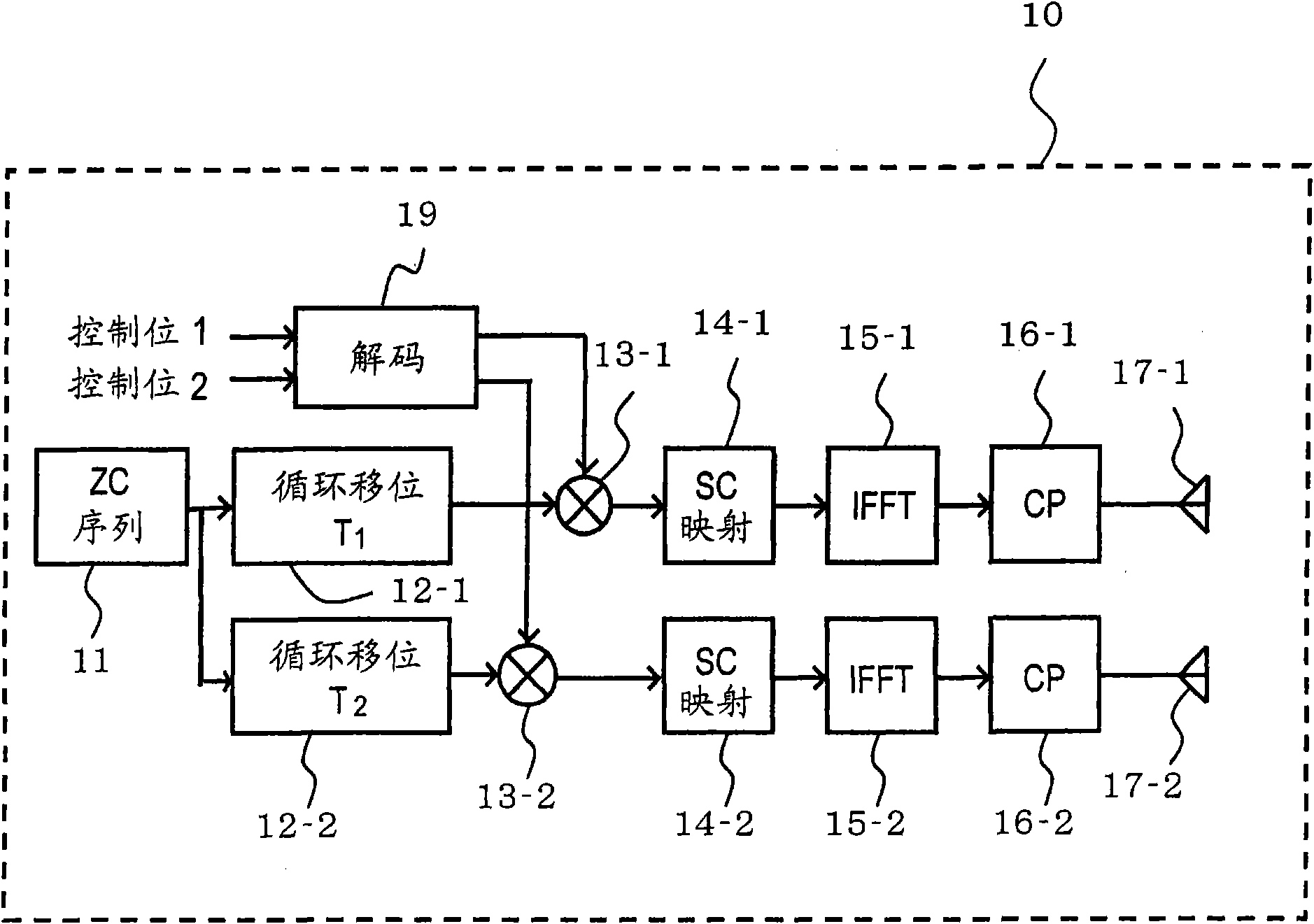
[0026] Preferred embodiments of the present invention are explained with reference to the drawings. Figure 1A and Figure 1B are diagrams each depicting a configuration example of a transmission device 10 that transmits a control channel such as PUCCH and a reception device 20 that receives the control channel. The transmitting device 10 is a device on the transmitting side of the wireless communication device, and the receiving device 20 is a device on the receiving side of the wireless communication device. For example, the transmitting device 10 is a terminal device, and the receiving device 20 is a base station device.

[0027] The transmitting device 10 includes a ZC sequence generation unit 11, cyclic shift units 12-1 and 12-2, modulation units 13-1 and 13-2, subcarrier mapping units 14-1 and 14-2, IFFT units 15-1 and 15-2, CP adding units 16-1 and 16-2, and transmitting antennas 17-1 and 17-2.

[0028] On the other hand, receiving apparatus 20 includes receiving ant...


PUM


Abstract

The invention provides a control channel transmission method in a radio communication apparatus which has a plurality of antennas, including, generating signals which are orthogonal to each other on a frequency axis between each of the antennas; modulating the signals using a control signal corresponding to a control channel respectively; and transmitting the modulated signals from each of the antennas using a single carrier transmission.

Description

technical field [0001] Embodiments discussed herein relate to control channel transmission methods and wireless communication devices. Background technique [0002] LTE (Long Term Evolution) is being considered as a next-generation communication method for third-generation portable phones. In LTE, uplink control information is transmitted using a control channel called "PUCCH (Physical Uplink Control Channel)". For example, ACK / NACK for downlink packet transmission, and CQI as downlink quality information are transmitted using the PUCCH. [0003] Figure 6 is a diagram depicting one example of the frame format of PUCCH. A subframe of 1 ms is divided into two blocks, and each divided block consists of seven blocks (FFT blocks). For example, if Figure 6 As shown, the second and sixth blocks of each time slot include a reference signal (see eg TS36.211 V8.0). PUSCH (Physical Uplink Shared Channel) is a channel for transmitting data, and is allocated to each subframe of eac...

Claims


Application Information

Patent Timeline
Patent Type & Authority Applications(China)
IPC IPC(8): H04L27/26H04L1/06
CPCH04L5/0053H04J11/00H04L27/2614
Inventor 木村大
Owner FUJITSU LTD
Why Eureka
Try Eureka