Circuit board fastening structure

a technology of circuit boards and fastening parts, applied in the direction of electrical apparatus casings/cabinets/drawers, instruments, computing, etc., can solve the problem of most time-consuming assembly

Active Publication Date: 2008-08-19
MITAC INT CORP
View PDF7 Cites 6 Cited by
  • Summary
  • Abstract
  • Description
  • Claims
  • Application Information

AI Technical Summary

Benefits of technology

[0007]The primary object of the invention is to provide a circuit board fastening structure to rapidly and securely fasten a circuit board to the seat of a chassis without using tools.

Problems solved by technology

This is the most commonly used approach, but is also the most time-consuming for assembly.

Method used


Image

  • Circuit board fastening structure
  • Circuit board fastening structure
  • Circuit board fastening structure

Examples


Embodiment Construction

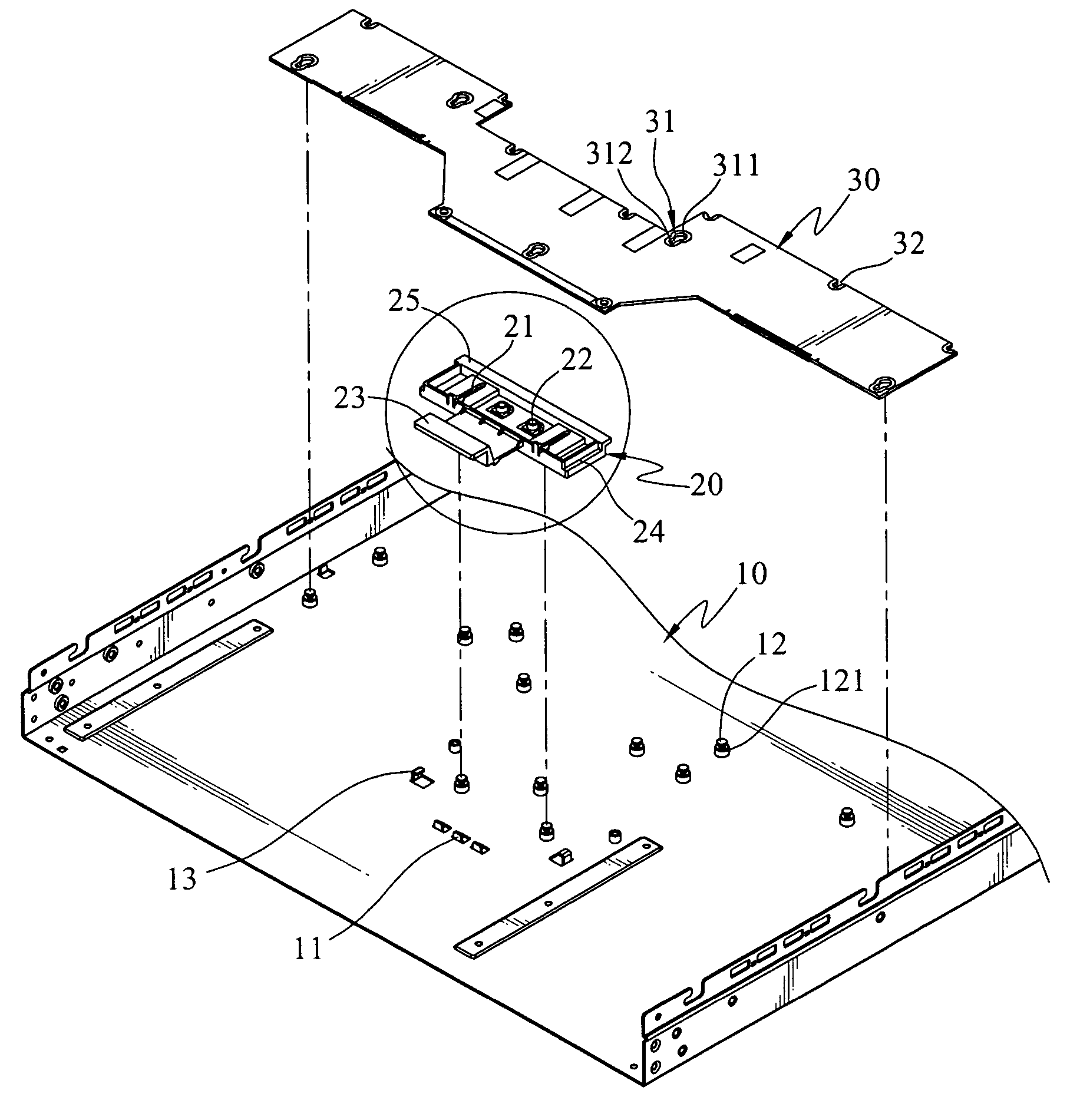
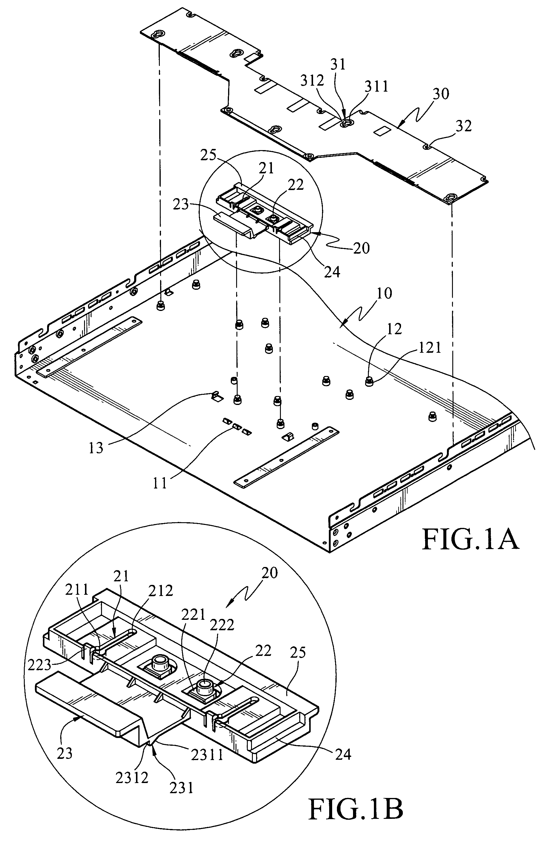
[0014]Referring to FIGS. 1A, 1B and 2, the circuit board fastening structure according to the invention includes a seat 10, a fastening plate 20 and a circuit board 30.

[0015]The seat 10 has a jutting detent wall 11, a plurality of anchoring members 12 and guiding tracks 13. The detent wall 11 is formed by a stamping method. Each of the anchoring members 12 has a groove 121 formed at a length at least equal to the thickness of the fastening plate 20 or the circuit board 30. The guiding tracks 13 are formed by a stamping method and opposite to each other for corresponding to two opposite sides of the fastening plate 20.

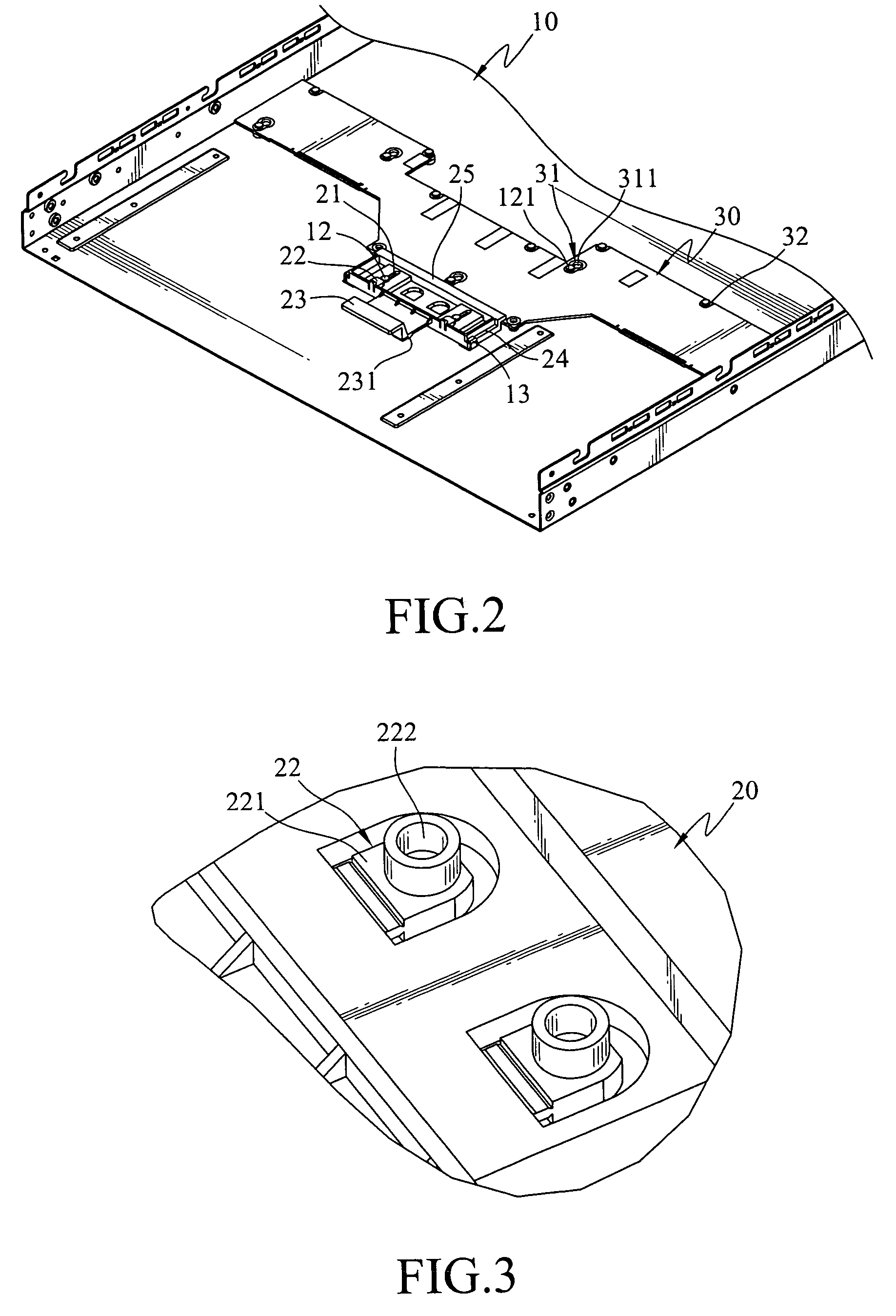
[0016]The fastening plate 20 is made of plastic. It has a plurality of gourd-shaped slots 21 and a flexible detent portion 22, a push portion 23, guiding channels 24 and a buffer member 25 (referring to FIG. 3 for the flexible detent portion).

[0017]Each of the gourd-shaped slots 21 includes an aperture 211 and a slit 212. The aperture 211 has a diameter greater than the...


PUM


Abstract

A circuit board fastening structure includes a seat, a fastening plate movably mounted onto the seat, and a circuit board. Anchoring members are provided to confine the circuit board. The seat has a detent wall to anchor a detent member located on the fastening plate so that the fastening plate and the circuit board may be coupled and anchored securely.

Description

CROSS-REFERENCE TO RELATED APPLICATIONS[0001]This non-provisional application claims priority under 35 U.S.C. § 119(a) on Patent Application No(s). 94102952 filed in Taiwan, R.O.C. on Jan. 31, 2005, the entire contents of which are hereby incorporated by reference.FIELD OF THE INVENTION[0002]The invention relates to a circuit board fastening structure, and particularly to a circuit board fastening structure for mounting a circuit board rapidly and securely without using hand tools.BACKGROUND OF THE INVENTION[0003]With the rapid development of technology, electronic devices are widely used by people in all walks of life. An electronic device generally includes one or more circuit boards to execute different functions, such as computers, digital cameras, personal digital assistants, personal music players, mobile phones and the like. Now many electronic devices have become household articles for everyday use.[0004]In general, the circuit board is fastened to the chassis of an electron...

Claims


Application Information

Patent Timeline
Patent Type & Authority Patents(United States)
IPC IPC(8): H05K7/02H05K7/04
CPCG06F1/184H05K7/142G06F1/185
Inventor TSAI, CHENG-YU
Owner MITAC INT CORP
Why Eureka
Try Eureka